Building with Kondo Kagaku KRS servos (RCB-4mini version)#
The chapter 13 quadruped can also be built with Kondo Kagaku ICS servos (KRS-3302 ICS) instead of Feetech’s STS3215. The servos all connect to Kondo Kagaku’s control board, the RCB-4mini, and the Arduino asks the RCB-4mini to “go to this angle”. The firmware’s control loop and the trained policy are the same ones that run on the Feetech version.
Note
The 3D-printed body and leg parts are shaped to fit the KRS servos and differ from the Feetech version’s STLs (the STLs are in Bill of materials (BOM) — KRS version 8-DoF quadruped). This page covers preparing the servos, assembling with the 3D viewer, wiring and flashing.
Updated body design (version 2)#
The 3D viewer, the step figures and the STLs show version 2 of the body, with the changes below. The photos and videos on this page were taken with version 1, so the body looks slightly different (the wiring and assembly are the same).
Version 1 |
Version 2 |
|
|---|---|---|
Hip servo orientation |
All four facing the same way (front and rear asymmetric) |
Front–rear symmetric. All four have their cases facing the centre of the body |
Hip spacing (front to rear) |
150 mm (−90 / +60 mm) |
132 mm (±66 mm) |
Body size |
230 × 110 × 50 mm |
176 × 110 × 50 mm. Also prints on a Bambu Lab A1 mini (180 mm square) |
Battery |
— |
Inside the body, laid flat in the 27 mm gap under the Arduino |
Lid |
None |
Snap-fit lid (head-shaped, taller at the front). No screws; four clips hook into windows in the body |
Board mounting |
Snap hooks (zero clearance) |
Added 0.4 mm clearance under the clips and 0.2 mm at the sides, and thickened the clip tips to 0.8 mm (4 layers) |
The hip servos were made front–rear symmetric because the KRS-3302 can measure its angle only within ±135 degrees of centre (see “Why centre it?” below). This way the front and rear legs use the same range of angles. The round hole and mount at the front of the body are for attaching a camera (Arducam B0642); they are not in the parts list or the steps.
Differences from the Feetech version#
Feetech version |
KRS version (this page) |
|
|---|---|---|
Servos |
STS3215 ×8 |
KRS-3302 ICS ×8 |
Board the servos connect to |
Waveshare Bus Servo Adapter (A) |
Kondo Kagaku RCB-4mini |
Tool for setting IDs |
The board’s USB and the |
Dual USB Adapter HS and the |
Wiring to the Arduino |
D0 / D1 (Serial1) |
D8 / D9 (leave D0 / D1 free) |
Power |
12 V |
Kondo Kagaku AC adapter (5.9 V), or a ROBO Power Cell E type (Ni-MH 7.2 V) to walk without a cable. The Arduino runs from the same supply |
Flashing |
|
|
How to set IDs and which ID goes on which joint are the same as the Feetech version.
What you need#
Bill of materials (BOM) — KRS version 8-DoF quadruped has the parts list, with links to Kondo Kagaku’s product pages and prices. To buy the Kondo Kagaku parts in one go, the KXR Advanced Set B Ver.2 is recommended: it includes 18 servos, the RCB-4mini, the Dual USB Adapter HS, a battery and a charger.
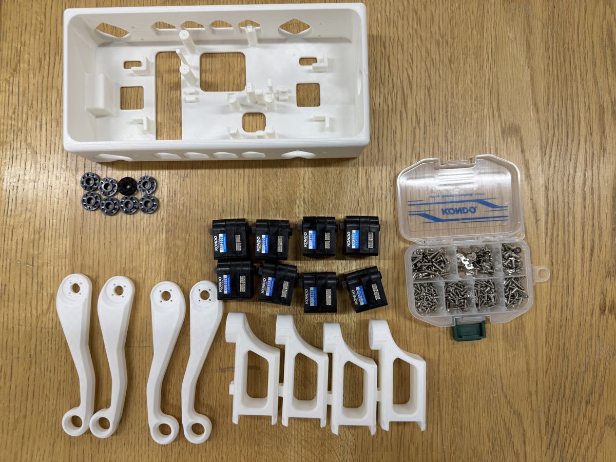
All the parts: the KRS version’s 3D-printed parts, KRS-3302 ICS ×8, horns and screws#
Using the Dual USB Adapter HS#
The Dual USB Adapter HS is Kondo Kagaku’s own adapter for connecting a PC to servos (or an RCB-4) over USB. It switches between two modes: ICS mode (talks to servos) and serial mode (talks to an RCB-4). This page uses ICS mode only.
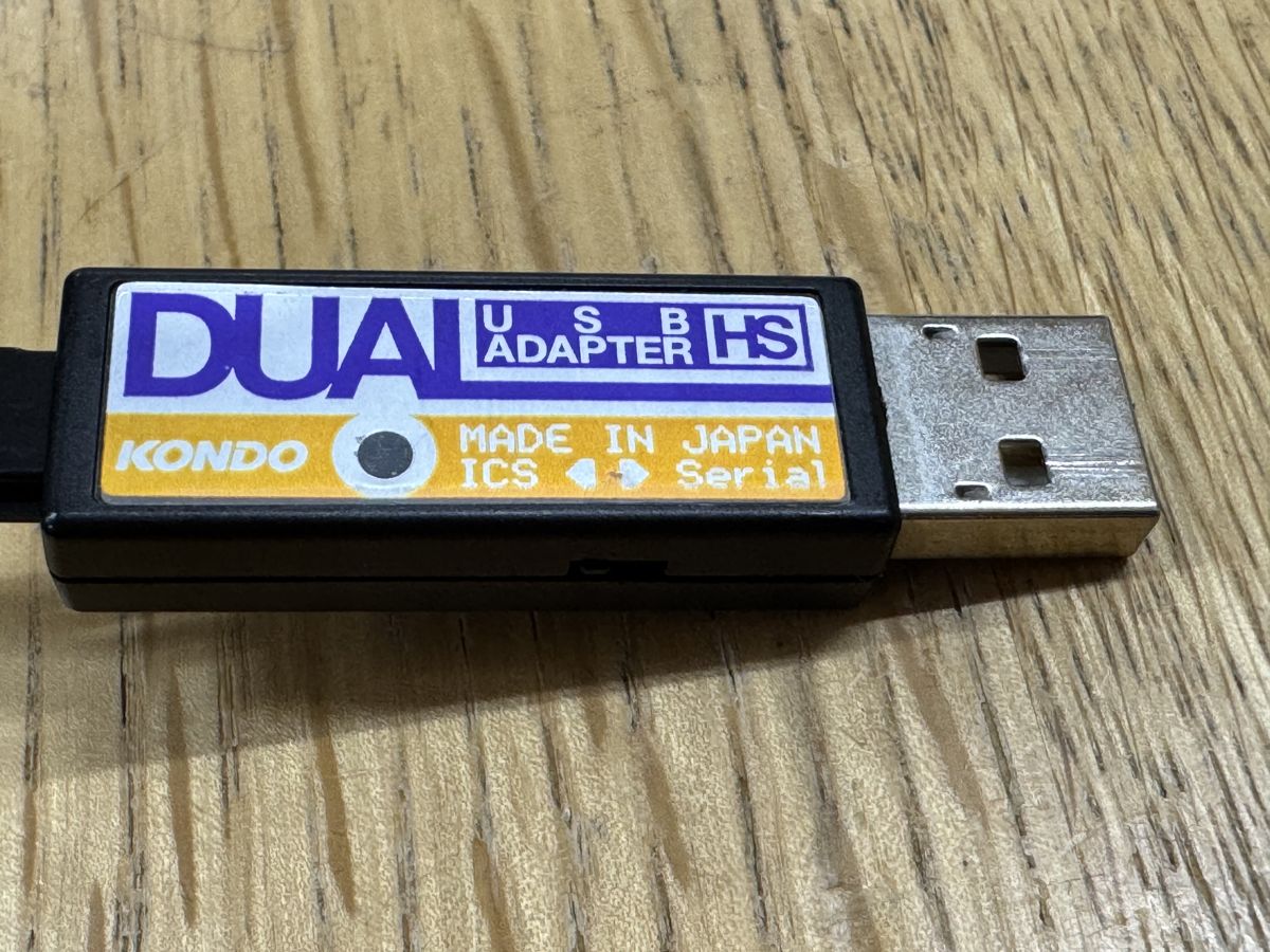
The Dual USB Adapter HS. A switch selects ICS / Serial#
Put it in ICS mode. A red LED means ICS mode; green means serial mode.
Connect just one servo to the adapter’s cable.
Plug the adapter into the PC’s USB port.
Connect one servo at a time
When setting IDs, connect exactly one servo to the PC. New servos all arrive with the same ID (1 for Feetech, 0 for Kondo Kagaku). With two or more servos at the same ID connected, they all answer at once, the signals collide and nothing can be read correctly. Writing an ID in that state changes every connected servo to the same new ID.
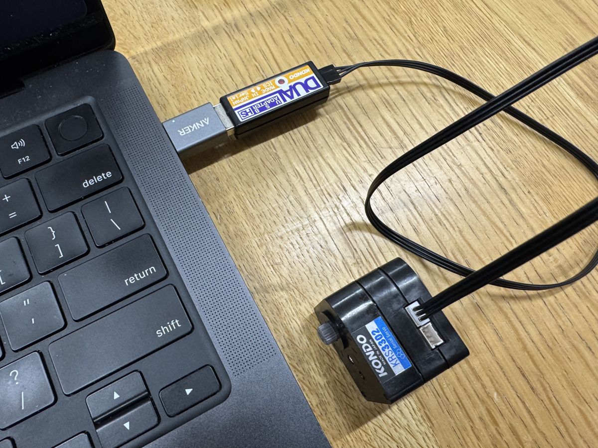
PC → Dual USB Adapter HS → one KRS-3302. This is how you set the IDs#
Preparing each OS#
On macOS and Linux, use ics-manager, installed below. On Windows, use Kondo Kagaku’s
official software, ICS3.5/3.6 Manager.
OS |
Software |
Preparation |
|---|---|---|
Windows |
ICS3.5/3.6 Manager (official, from Kondo Kagaku) |
Install the adapter’s driver (KO Driver). For usage, see Kondo Kagaku’s guide |
macOS |
|
|
Linux |
|
Make the adapter show up as an FTDI serial device. Run the commands below once |
On Linux, ics-manager prints these steps itself when it cannot connect.
$ sudo su
# modprobe ftdi-sio
# echo 165C 0008 > /sys/bus/usb-serial/drivers/ftdi_sio/new_id
# exit
With ICS3.5/3.6 Manager on Windows, the items to check (ID, bus speed, continuous rotation mode, reverse mode) are the same as below.
Checking the servo settings and setting the IDs#
Install ics-manager#
ics-manager is a command for reading and writing an ICS servo’s ID and settings.
It is part of the Python package rcb4.
With the uv you installed while setting up, one line installs it
(if you do not have uv yet, see “Install uv” for macOS /
Linux first).
$ uv tool install rcb4
Reading the screen#
With just one servo connected, running ics-manager shows the screen below.
Do not run it with two or more connected (see “Connect one servo at a time” above).
$ ics-manager
--- Servo Status ---
>>  Current Servo ID: 2 -> Next Servo ID: [0 1 2 3 4 5 6 7 8 9 10 11 12 13 14 15 16 17 ]
    Angle: -44
    Speed: 127
    Stretch: 90
    Baud Rate: 1.25Mbps
    Rotation Mode: Disabled
    Slave Mode: Disabled
    Reverse Mode: Disabled
    Serial Mode: Disabled
    Free: Enabled
----------------------
For this quadruped, always check these four lines.
Line |
Correct value for this robot |
What goes wrong otherwise |
|---|---|---|
|
The ID from the table below (1–8) |
Commands reach a different joint |
|
|
The RCB-4mini cannot talk to it, and only that servo is not found |
|
|
|
|
|
|
Free: Enabled means the servo is limp (no torque), which is fine while setting IDs.
Angle is the output shaft’s current angle (in degrees); it changes when you turn the
shaft by hand.
Set the ID#
Check that
>>is on theCurrent Servo IDline (move with ↑↓).Use ←→ to set the green number to the new ID and press Enter.
Check that the number to the left of
Current Servo ID:has changed to the new ID.Check that
Rotation ModeandReverse ModeareDisabledandBaud Rateis1.25Mbps.Quit with
qand put an ID label on the servo. A label on a face that stays visible after assembly saves trouble later, when wiring or replacing a servo.Connect the next servo and go back to step 1.

Steps 1 to 3 on real hardware. Setting the green number to 2 with → and pressing Enter turns the ID 3 servo into ID 2#
The ID is written to the EEPROM inside the servo, so it survives a power cycle.
Column: what is EEPROM?
EEPROM is a small memory that keeps its contents when the power is off. Servos have one inside, and it holds “that servo’s settings” such as its ID, bus speed and direction of rotation. The servo reads its settings from EEPROM every time it powers up, so an ID written once stays after the power is turned off.
Values used only while running, such as the current angle and the target angle, live in memory that is cleared when the power goes off (RAM).
If Rotation Mode or Reverse Mode is Enabled#
Rotation Mode toggles with the
rkey. Press it until it showsDisabled.Reverse Mode toggles with the
vkey. Press it until it showsDisabled. The servo is made limp before switching, so the shaft does not move suddenly.
Each press writes to EEPROM, and the screen shows the result, such as
Rotation mode set to Disabled.
Which servo goes where#
The ID assignment is the same as the Feetech version.

Servo ID assignment. Seen from above, the front is the end with the tab in the middle of the body’s short side#
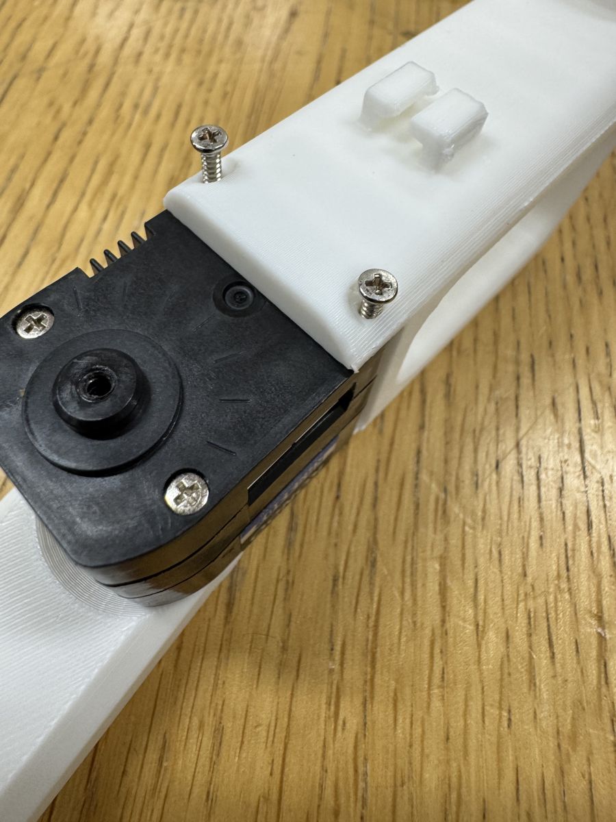
Centre the servo before fitting the horn and leg#
A horn goes on the servo’s output shaft, and the leg is screwed to the horn.
Column: what is a servo horn?
A servo horn (or just horn) is the disc- or arm-shaped part fitted onto the servo’s output shaft. It passes the servo’s rotation on to the part it drives, such as a leg. The tip of the output shaft has fine teeth (a spline), and the inside of the horn’s hole has the same teeth. The teeth mesh and a screw holds them together, so the force is transmitted without slipping.
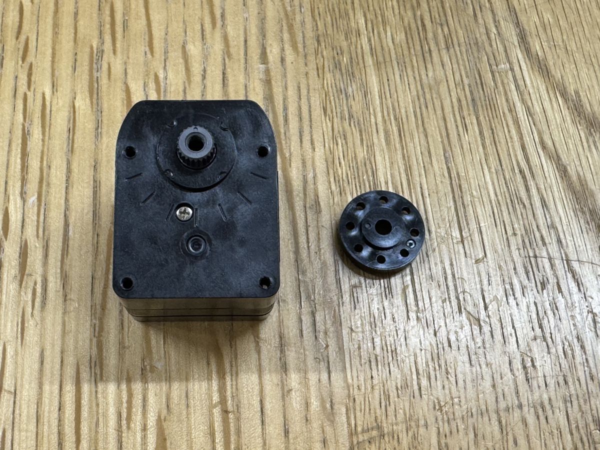
The mesh can only be shifted one tooth at a time, so the direction in which you fit the horn decides “which way the leg points when the servo is at its centre angle”.
The direction in which you fit the horn is decided after moving the servo to its centre angle (0 degrees).
Connect the servo to the Dual USB Adapter and run
ics-manager.Press
z. The servo moves to its centre angle (0 degrees, 7500 as a pulse value) and holds there.In that state, fit the horn so that the leg points straight down (0 degrees in the CAD) and fix it with the supplied M3-6 low-head horn screw. For the knee, screw the horn to the foot first and fit it together with the foot (see Assembly below).
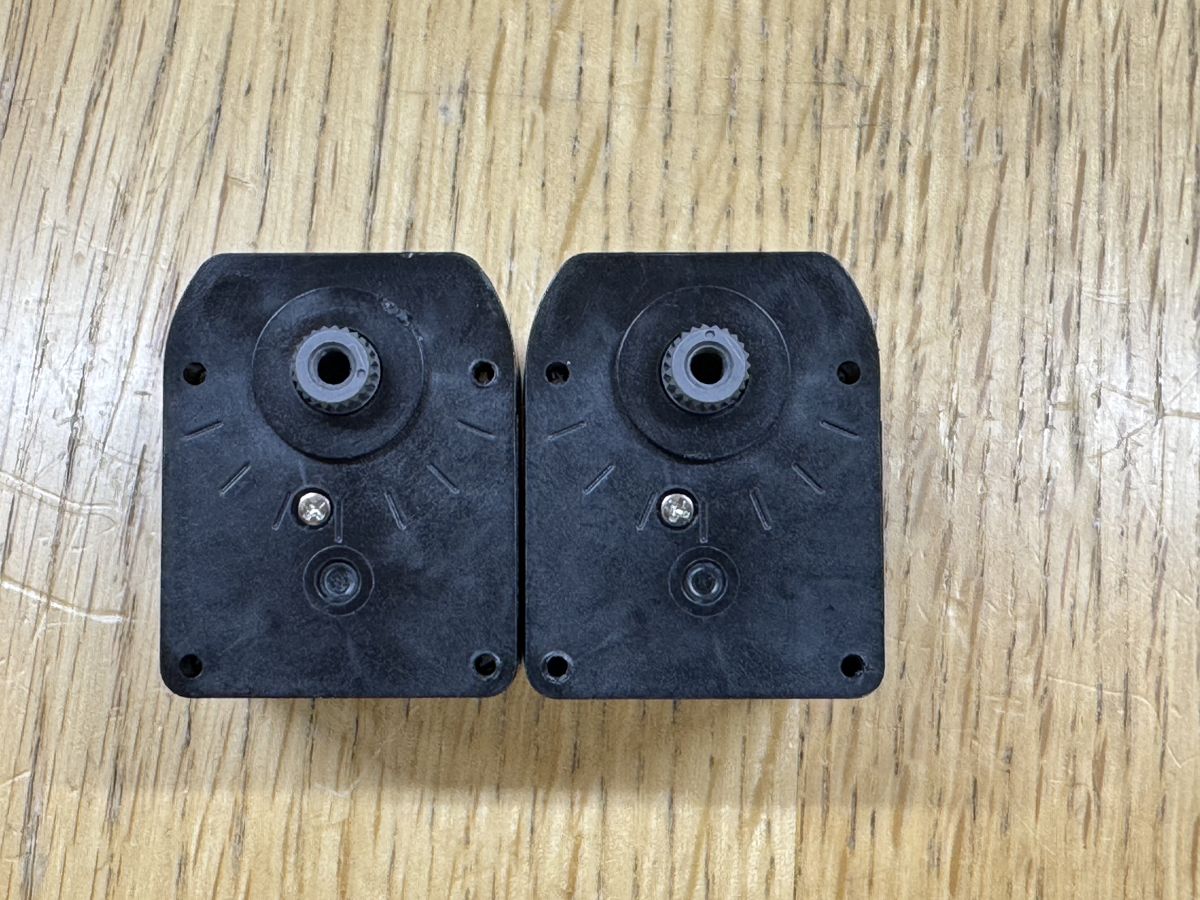
Servos before the horn is fitted. The output shaft is toothed (a spline), and the horn can only be fitted in steps of one tooth#
Why centre it?#
The KRS-3302 can measure its angle only within ±135 degrees (270 degrees in total) of centre.
Column: what is an encoder?
An encoder is a sensor that measures what angle a shaft is at right now. The servo compares the “target angle” with the “current angle” measured by the encoder and turns the motor so that the difference gets smaller. This is how a servo can hold still at an angle you command.
The range of angles an encoder can measure differs from servo to servo. At angles it cannot measure, the servo does not know where it is, so it cannot move there.
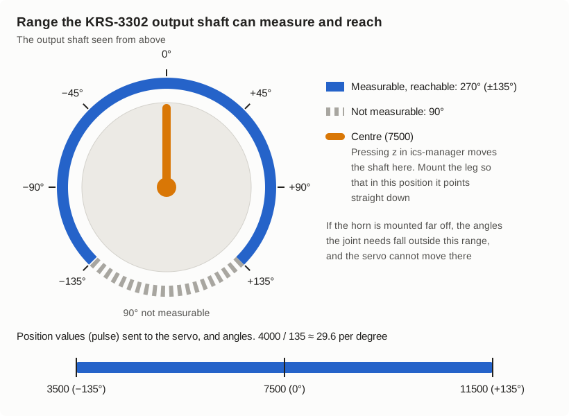
The range the KRS-3302 can measure and move through. If the leg is fitted to point straight down at centre (7500), the angles you want the joint to reach stay inside this range#
On this quadruped, bending the knee into the standing pose turns it about 100 degrees from where the leg is straight. With the straight-leg direction at centre, that angle also stays inside the 270-degree range. If the horn is fitted far off, the angles you want to bend to fall outside the range, and the servo cannot move there.
Being off by one tooth does not matter. After assembly you measure the servo values with the legs straight and write them into the firmware (see “Flash and calibrate” below), so small offsets are absorbed there.
Assembly#
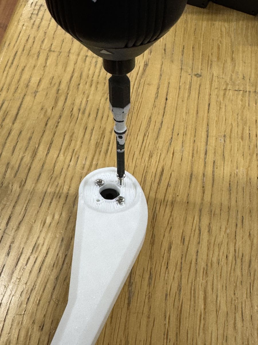
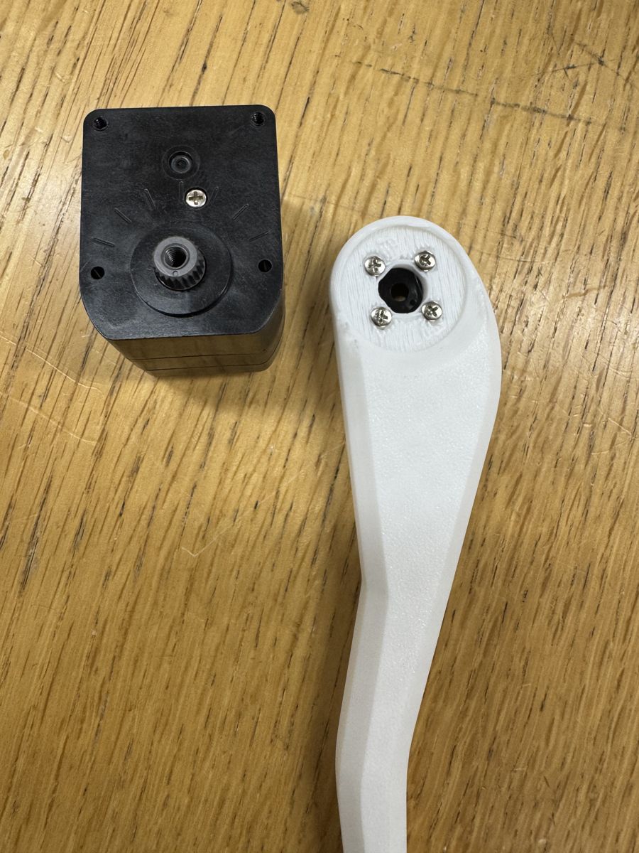
First build four kinds of units (hip servos with horns, the body with its servos, the feet and the legs), then attach the legs to the body and put the lid on. The feet (leg brackets) are screwed to their horns first, and then fitted onto the servo’s output shaft together with the horn. The steps and figures were generated automatically from the KRS version’s CAD, screws included.
Before fitting any horn onto a servo, centre the servo (0 degrees) as described in “Centre the servo before fitting the horn and leg” above.
Interactive 3D viewer#
Plays the assembly step by step as an animation in the browser. Drag to rotate the view and use the slider to step back and forth.
Screws#
All the screws are Kondo Kagaku’s, and their lengths follow the rules in Kondo Kagaku’s documentation.
Screw |
Qty |
Where |
How the length was chosen |
|---|---|---|---|
M3-6 low-head horn screw |
8 |
Horn → servo output shaft |
One comes with each servo (Kondo Kagaku’s manual, “Attaching the servo horn”) |
M2-8 low-head screw |
8 |
Body → hip servo’s upper case |
The upper case’s screw holes (φ1.6 pilot holes) have an effective depth of 4.8mm. The body wall is 3.7mm, so 8mm is the longest that reaches no more than 4.8mm in |
M2-6 low-head screw |
8 |
Leg link → knee servo’s upper case |
Same rule. The leg link is 2.0mm thick (from the bottom of the counterbore), so 6mm |
M2-6 low-head screw |
16 |
Leg bracket (foot) → knee horn |
The small-diameter horn B’s screw holes are M2 threaded and 2mm thick. Bracket 4.0mm + 2mm = 6mm |
M2-4 low-head screw |
16 |
Leg link → hip horn |
Leg link 2.0mm + horn 2mm = 4mm |
Case screw (2-20 low-head tapping screw) |
8 |
Leg link → knee servo’s bottom case |
No need to buy. Take out the case screws already fitted to the servo as it comes, fit the leg link, and fix it back with the same screws (as Kondo Kagaku specifies) |
The M2-4, M2-6 and M2-8 low-head screws and the M3-6 horn screws all come together in Kondo Kagaku’s Screw Set A (for KXR). The “flat head” screws (2.6-4 flat head screws) specified in Kondo Kagaku’s manual are for the free-horn side, which this robot does not use.
Warning
On the knee’s bottom case side, the case screw taken out of the servo (20mm) clamps the leg link as well (about 3.5mm from the bottom of the counterbore to the servo), so less of the case screw bites into the servo. Measured in CAD, about 1.8mm engages the pilot hole. Overtightening strips the pilot hole, so tighten it gently. Kondo Kagaku’s drawing is an example with a 1mm-thick frame.
Units#
There are 90 individual parts (11 kinds) in total.
Unit |
Qty |
Parts inside |
|---|---|---|
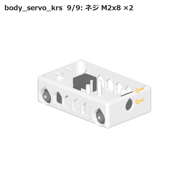
body_servo_krs (body + 4 hip servos with horns) |
×1 |
21 |
foot_left_krs / foot_right_krs (foot + horn) |
×2 each |
6 |
leg_left_krs / leg_right_krs (leg, including the foot) |
×2 each |
13 |
Add the 16 M2-4 low-head screws used in the final assembly and the lid, and that makes 90.
Part |
Qty |
|---|---|
M2-6 low-head screw |
×24 |
M2-4 low-head screw |
×16 |
Case screw (2-20 low-head tapping) |
×8 |
M2-8 low-head screw |
×8 |
M3-6 low-head horn screw |
×8 |
KRS-3302 ICS (KRS3300_scale in the figures) |
×8 |
Small-diameter horn B (small_diameter_hornB) |
×8 |
Leg bracket (bracket_outline_krs) |
×4 |
Leg link (leg_link1_krs) |
×4 |
Body (body_krs) |
×1 |
Lid (lid_krs) |
×1 |
KRS3300-1 to -4 in the figures are the CAD part numbers, not servo IDs. They correspond to the IDs in “Which servo goes where” above as follows.
Unit |
CAD number → position |
IDs to use |
|---|---|---|
body_servo_krs (body) |
KRS3300-3 → front right, KRS3300-4 → front left, KRS3300-1 → rear right, KRS3300-2 → rear left |
1 (front right), 3 (front left), 5 (rear right), 7 (rear left) |
leg_right_krs (right leg) ×2 |
the knees of the right legs |
2 (front right), 6 (rear right) |
leg_left_krs (left leg) ×2 |
the knees of the left legs |
4 (front left), 8 (rear left) |
Building the units#
Each kind of unit is shown once; ×N is how many the whole robot uses. Build them from top to bottom and you will have every unit you need. In the figures, the part and screws marked with an orange arrow are the ones fitted in that step.
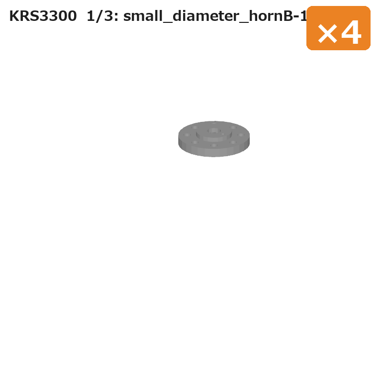
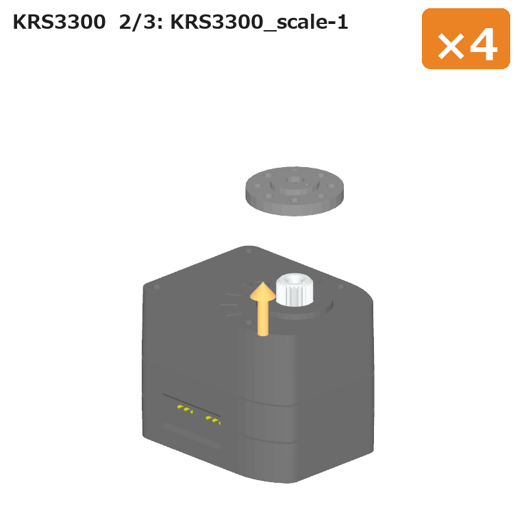
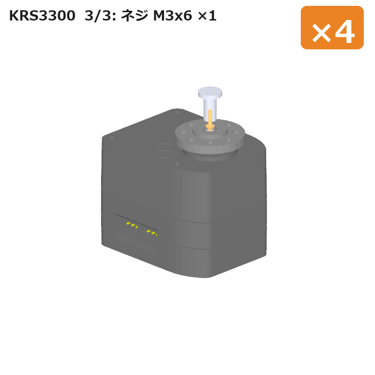
KRS3300 (fitting horns to the hip servos) ×4
Only the four hip servos (IDs 1, 3, 5, 7). The knee horns are fitted together with the feet (foot and leg below).
Place the small-diameter horn B (base).
Servo onto the horn — fit the centred servo’s output shaft into it.
🔩 Tighten M3-6 low-head horn screw ×1 (horn ↔ output shaft).
body_servo_krs (fixing 4 servos in the body) ×1
Parts: body ×1, hip servos with horns ×4, M2-8 low-head screws ×8
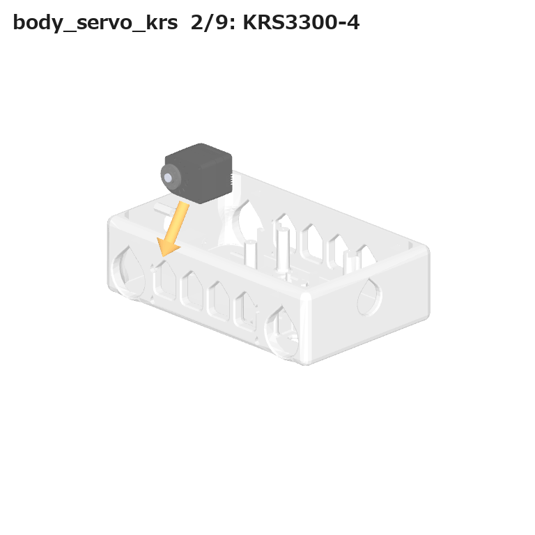
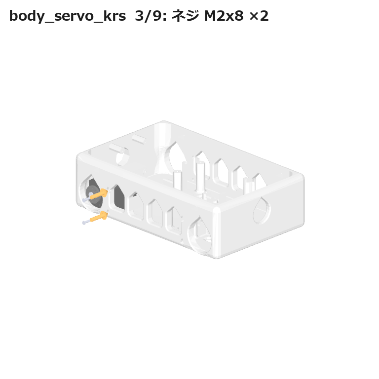
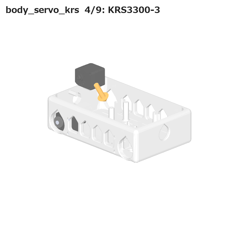
The servos go in from inside the body, with the horns sticking out through the round holes in the body wall. The screws go in from outside the body, through the wall, into the screw holes of the upper case (the output-shaft side).
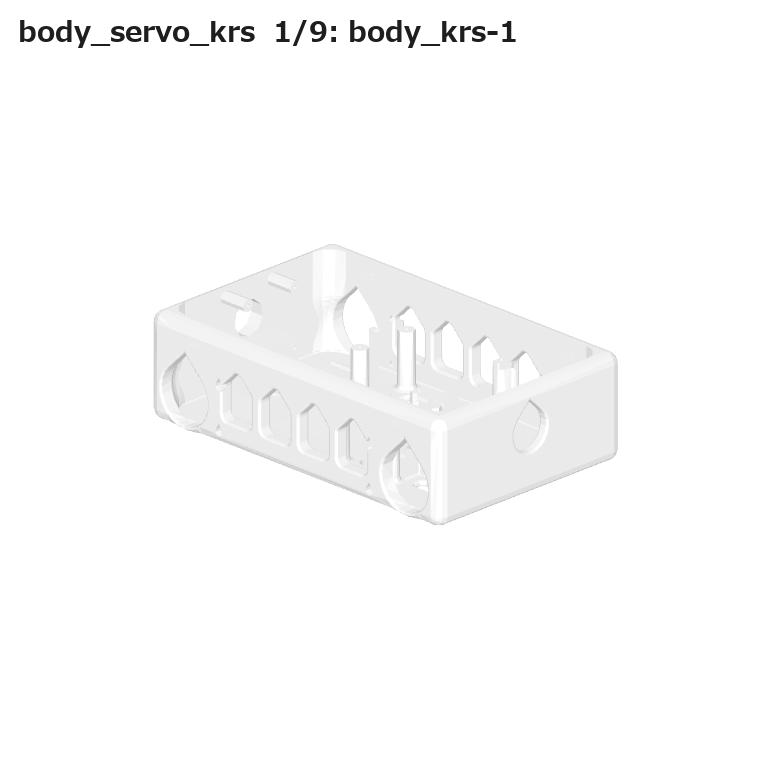
Place body_krs (the body) (base).
KRS3300-4 (front left, ID 3) — insert into the body (horn into the hole in the wall, coaxial φ2.3mm ×2, 2 mating faces).
🔩 Tighten M2-8 low-head screw ×2 (servo ↔ body).
KRS3300-3 (front right, ID 1) — insert into the body.
🔩 Tighten M2-8 low-head screw ×2.
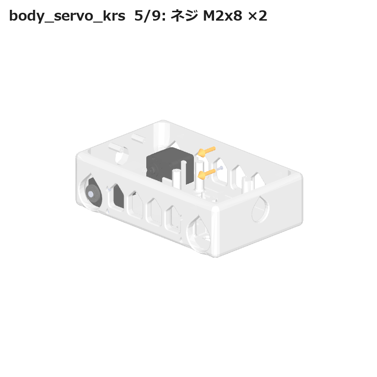
KRS3300-2 (rear left, ID 7) — insert into the body.
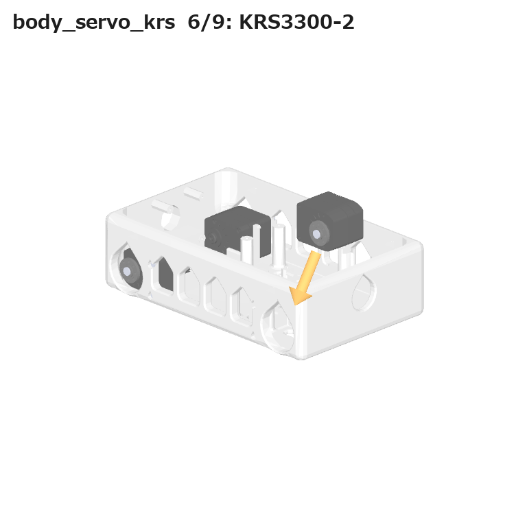
🔩 Tighten M2-8 low-head screw ×2.
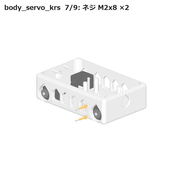
KRS3300-1 (rear right, ID 5) — insert into the body.
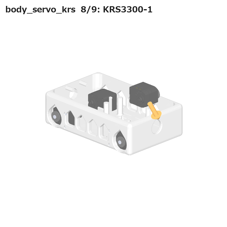
🔩 Tighten M2-8 low-head screw ×2.
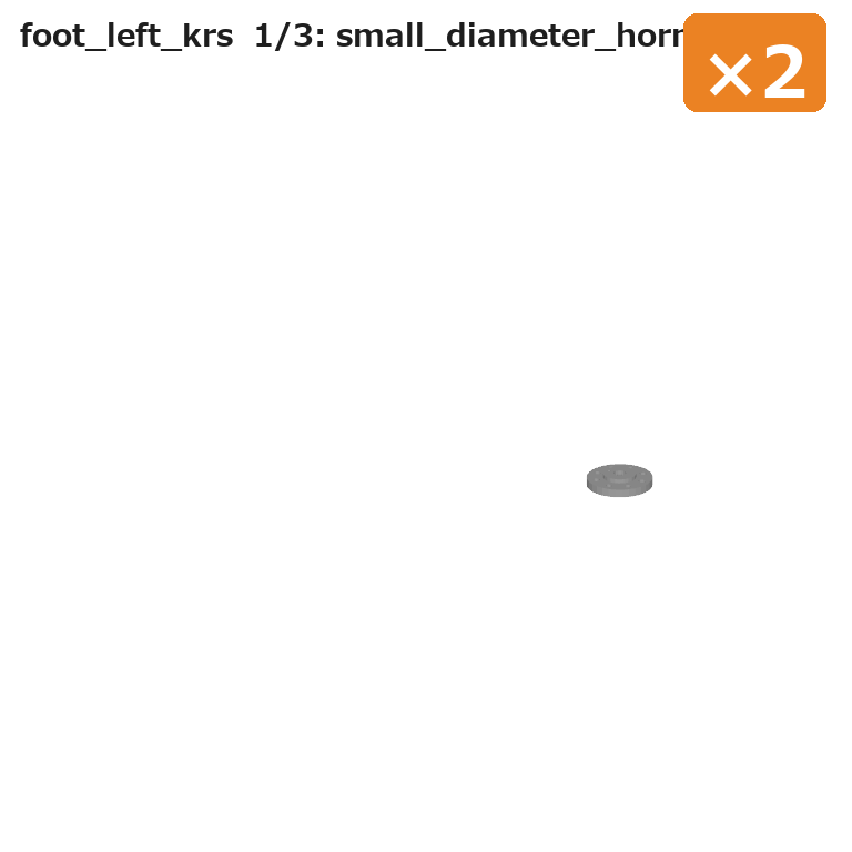
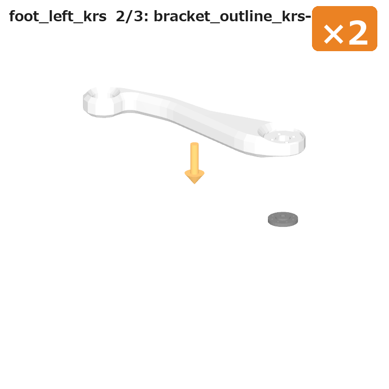
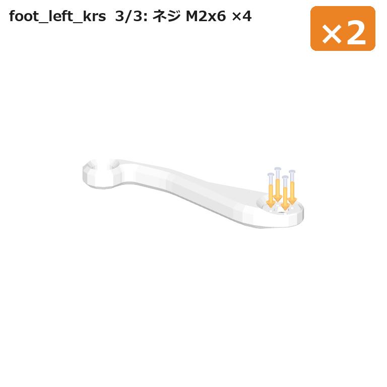
foot_left_krs / foot_right_krs (screwing the horn to the foot) ×2 each
Parts: leg bracket ×1, small-diameter horn B ×1, M2-6 low-head screws ×4
Before fitting it to the servo, screw the horn to the foot (leg bracket). The steps are the same for left and right; the face the horn goes on is mirrored.
Place the small-diameter horn B (base).
bracket_outline_krs (leg bracket) — line it up with the horn (coaxial φ8.4mm, coaxial φ2.3mm, mating face).
🔩 Tighten M2-6 low-head screw ×4 (leg bracket ↔ horn).
leg_left_krs / leg_right_krs (leg) ×2 each
Parts: knee servo (KRS-3302) ×1, foot ×1, leg link ×1, M3-6 low-head horn screw ×1, M2-6 low-head screws ×2, case screws ×2 (the ones already fitted to the servo). The right leg only differs in using foot_right_krs for the foot; the steps are the same.
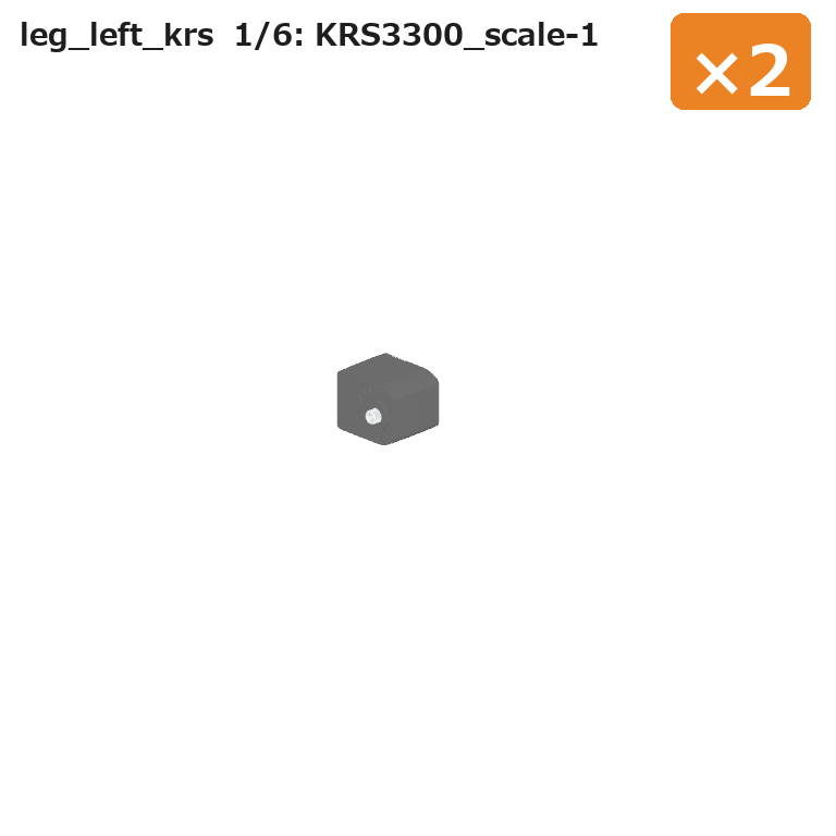
Place KRS3300_scale (the knee servo, centred beforehand) (base).
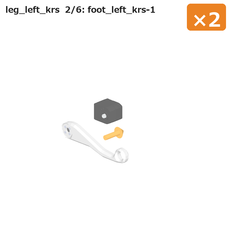
foot_left_krs (foot with horn) — fit the horn onto the output shaft with the leg pointing straight.
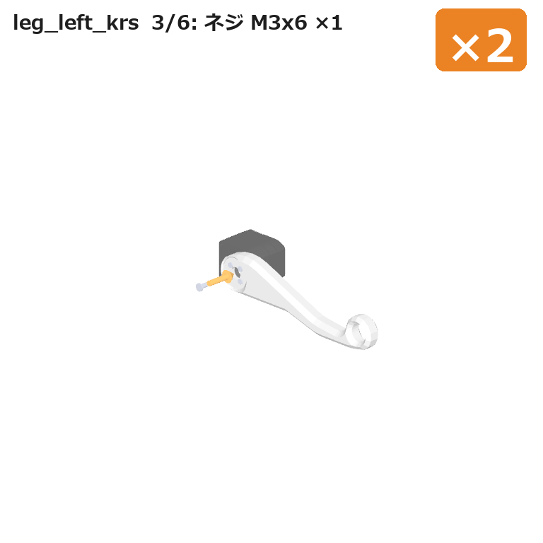
🔩 Tighten M3-6 low-head horn screw ×1 through the centre hole of the leg bracket (horn ↔ output shaft).
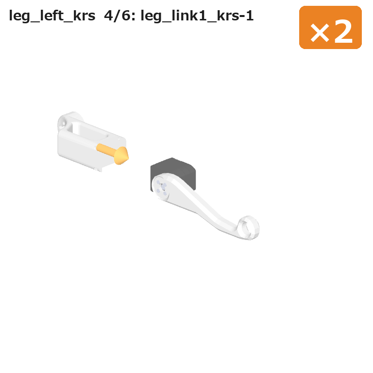
leg_link1_krs (leg link) — first, take out the two case screws on the servo’s bottom case side (opposite the output shaft) that line up with the holes in the leg link. Then slide the servo in between the leg link’s sides (coaxial φ2.3mm ×4, 2 mating faces).
🔩 Case screw ×2 — put the case screws you took out in step 4 through the leg link’s counterbores and tighten them back into the servo.
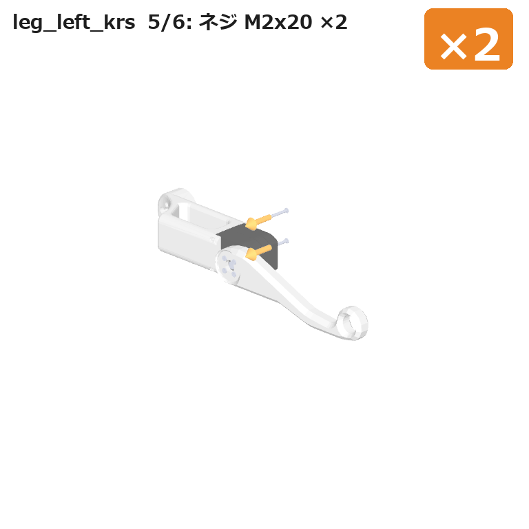
🔩 Tighten M2-6 low-head screw ×2 (leg link ↔ upper case).
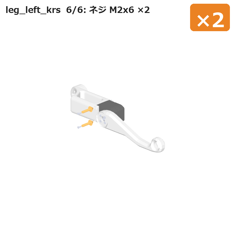
Final assembly#
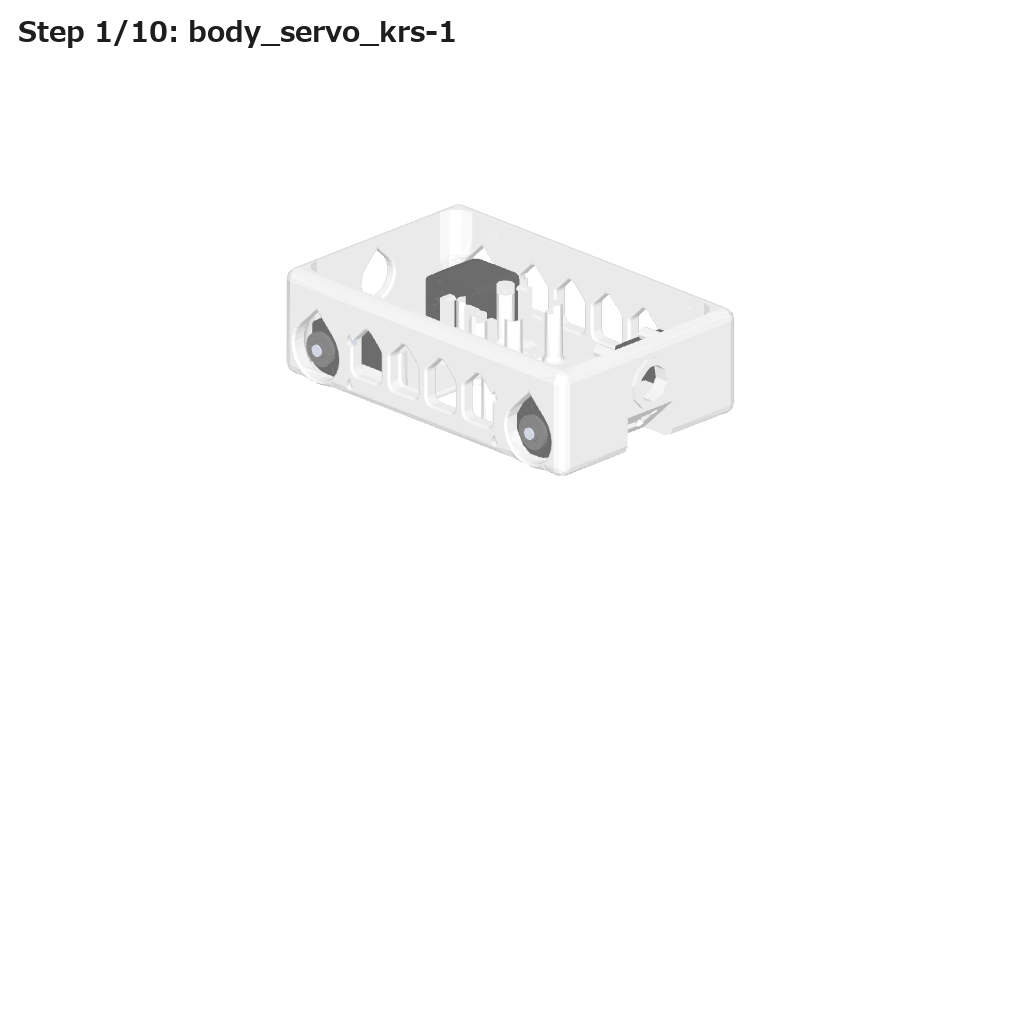
Attach the pre-built units to the body (body_servo_krs). Line up the top end of the leg link with the hip horn and fix it to the horn with M2-4 low-head screws through the holes on the outside of the leg link. Keep the hip servos centred too, and line the legs up so they point straight down.
Step 1: place body_servo_krs#
Step 2: attach leg_right_krs (first, front right)#
Line the leg link up with the front-right hip horn (KRS3300-3) (coaxial φ8.4mm, coaxial φ2.3mm ×2).
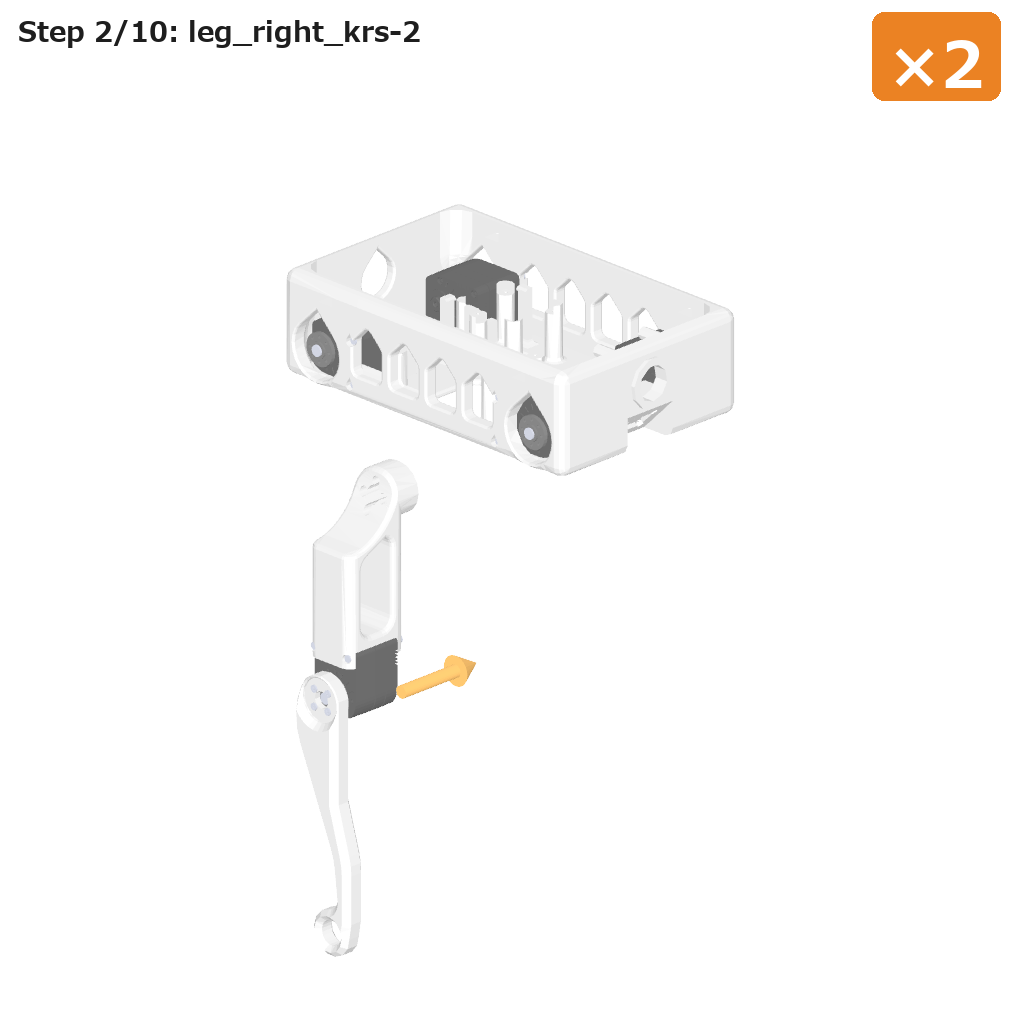
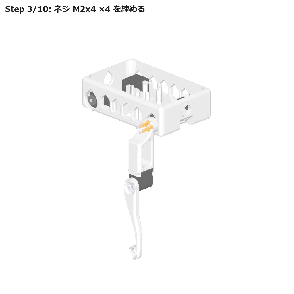
Step 3: 🔩 tighten M2-4 low-head screw ×4#
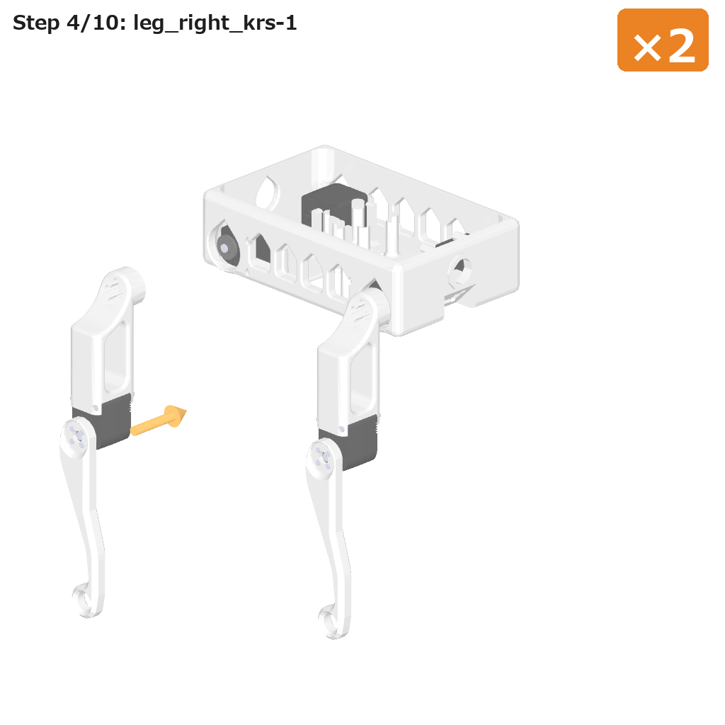
Step 4: attach leg_right_krs (second, rear right)#
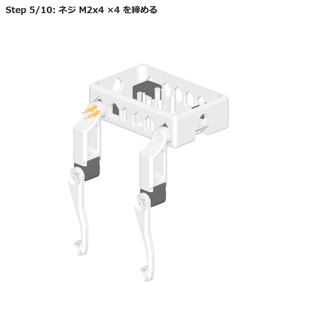
Step 5: 🔩 tighten M2-4 low-head screw ×4#
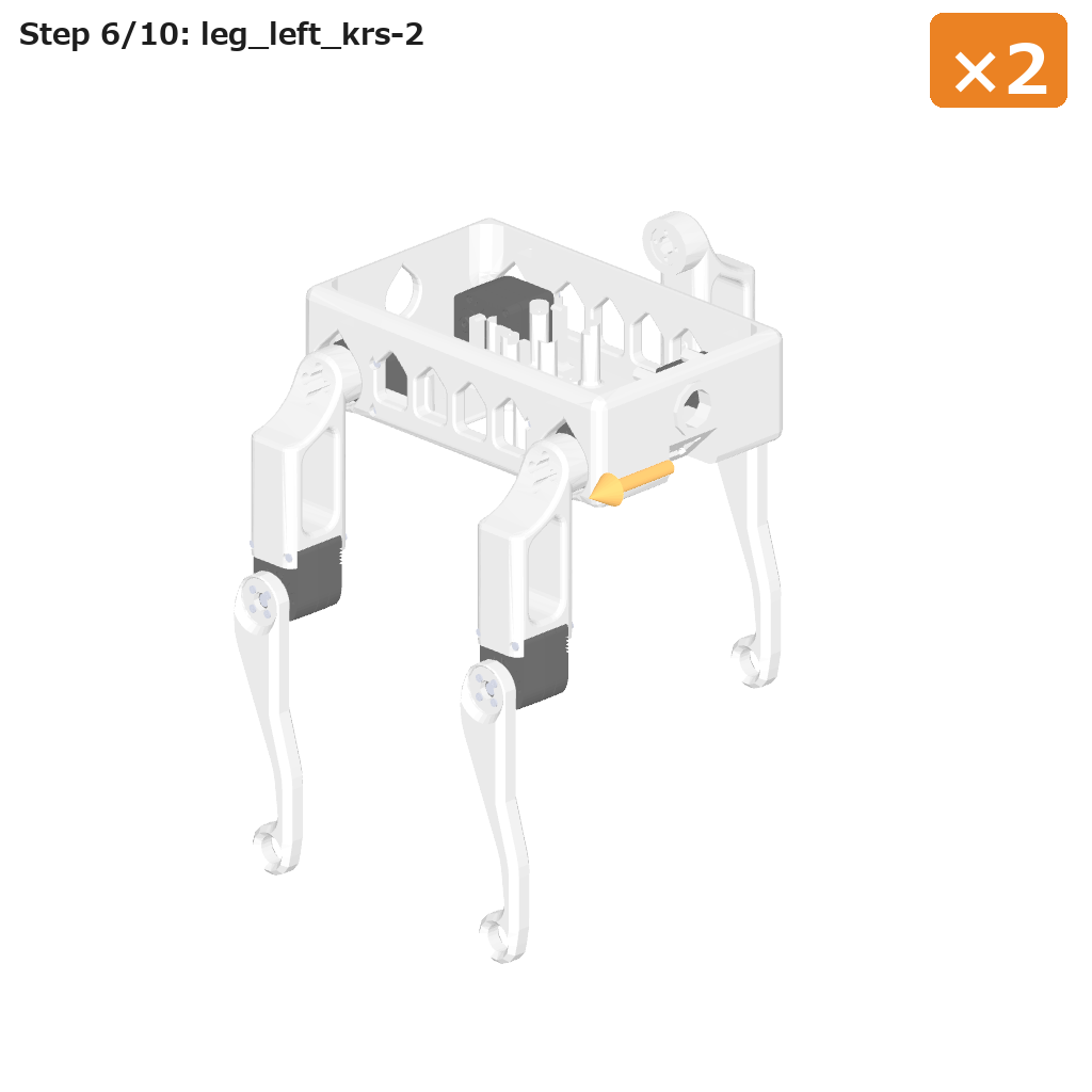
Step 6: attach leg_left_krs (first, rear left)#
Line it up with the hip horn on the other side. It goes in the opposite direction to the right legs.
Step 7: 🔩 tighten M2-4 low-head screw ×4#
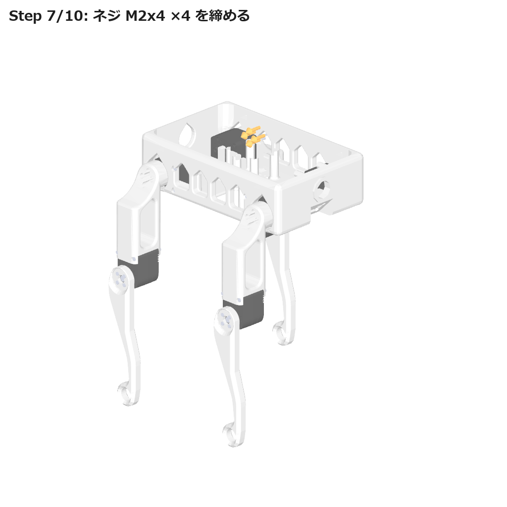
Step 8: attach leg_left_krs (second, front left)#
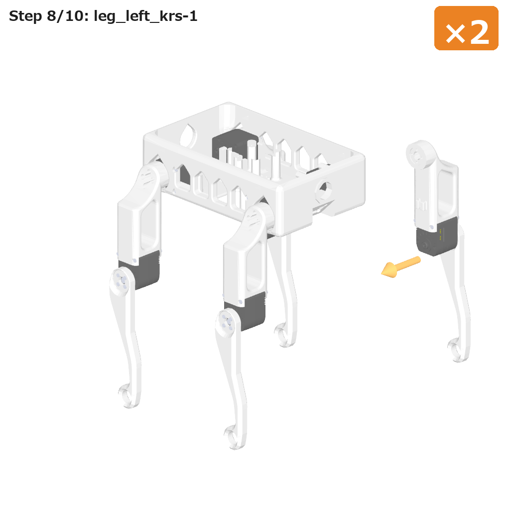
Step 9: 🔩 tighten M2-4 low-head screw ×4#
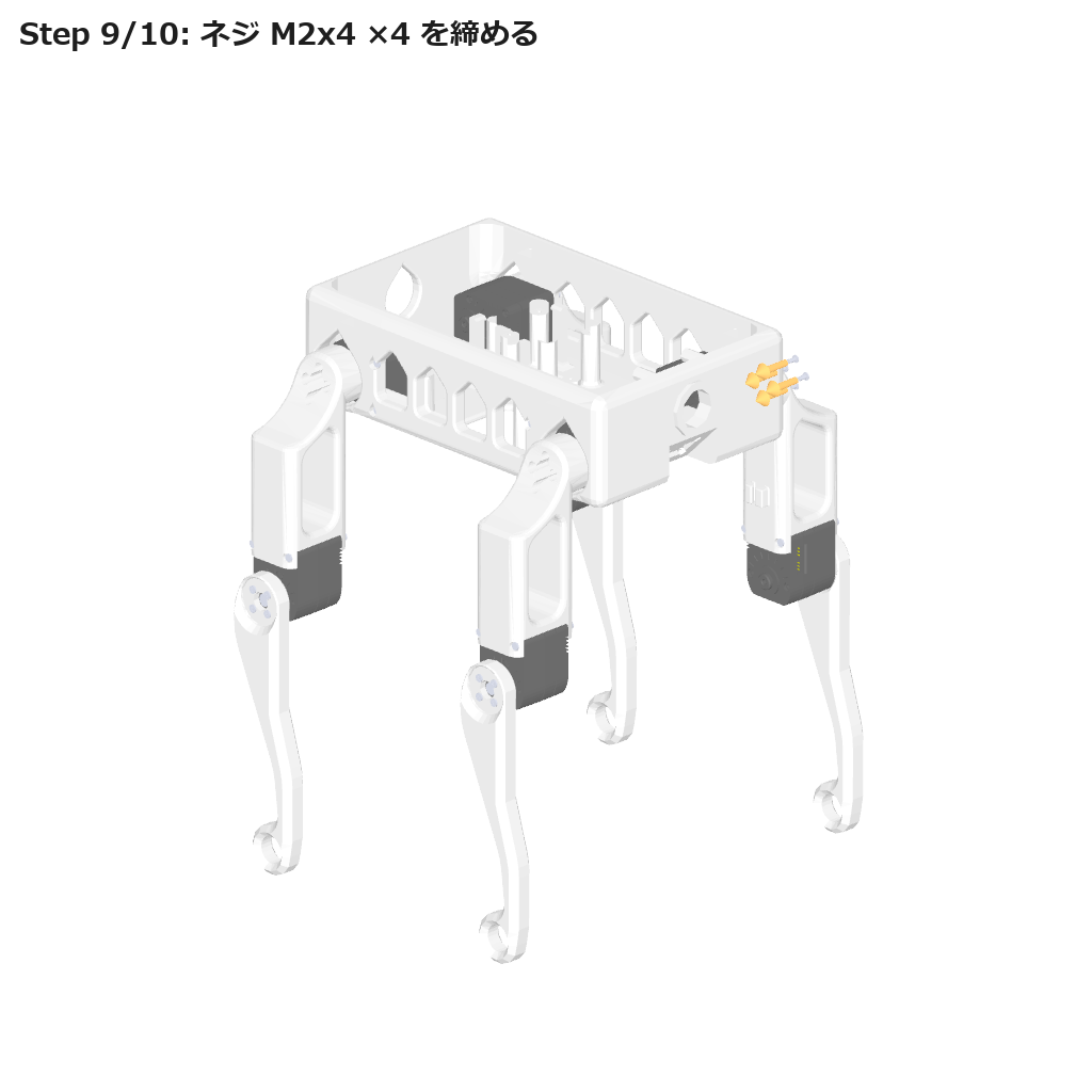
Step 10: put lid_krs (the lid) on#
The lid goes on last, after the wiring (“Wiring” below) is done and the battery and boards are inside the body. Line the edge of the lid up with the top edge of the body and press straight down; the two clips on each side snap into the windows in the body’s side walls (lid clip windows). To remove it, push the clip tips inwards through the side windows while lifting the lid. No screws are used.
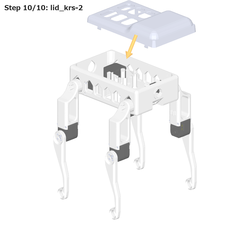
The robot is complete.
Fitting into the body#
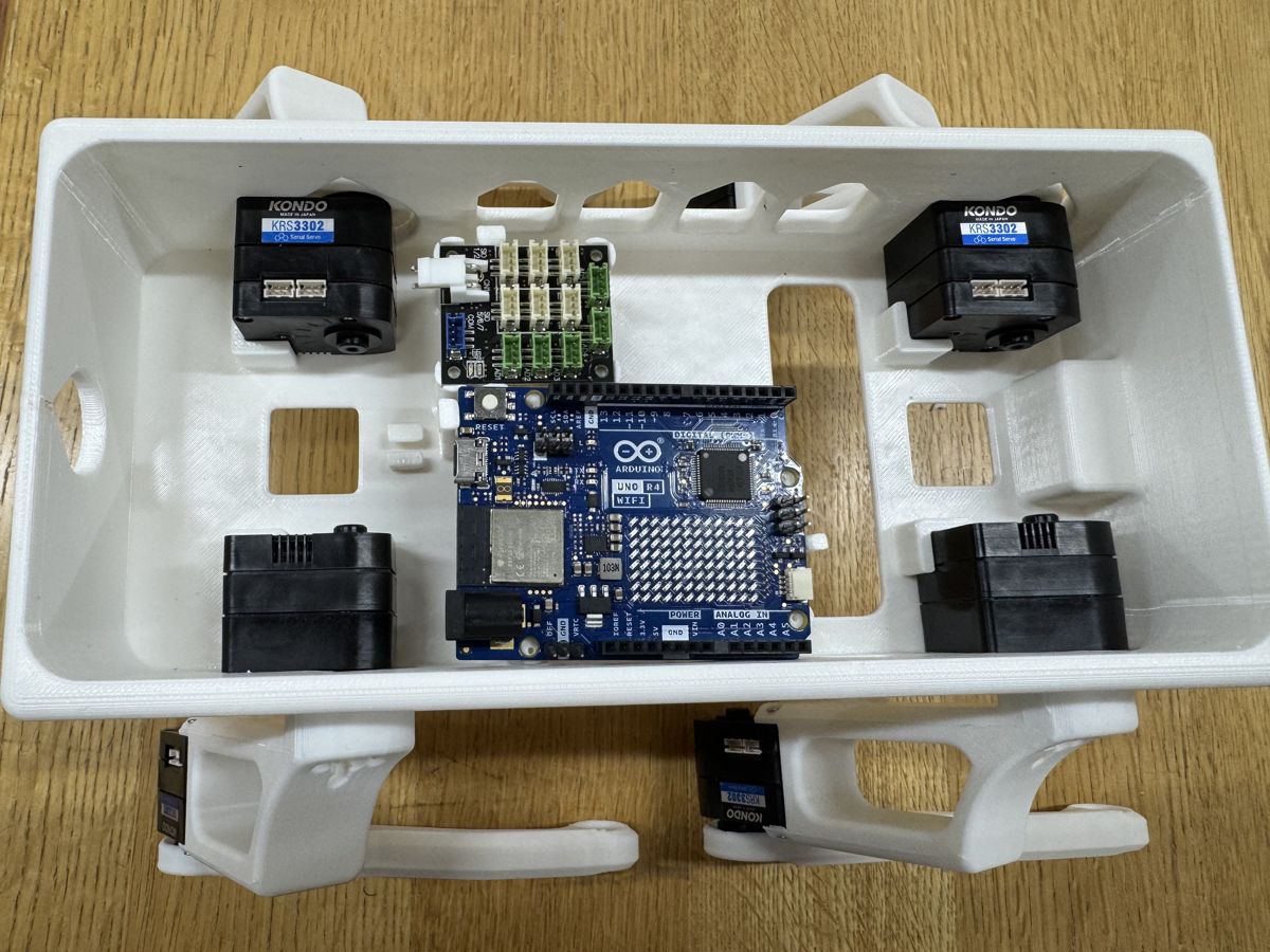
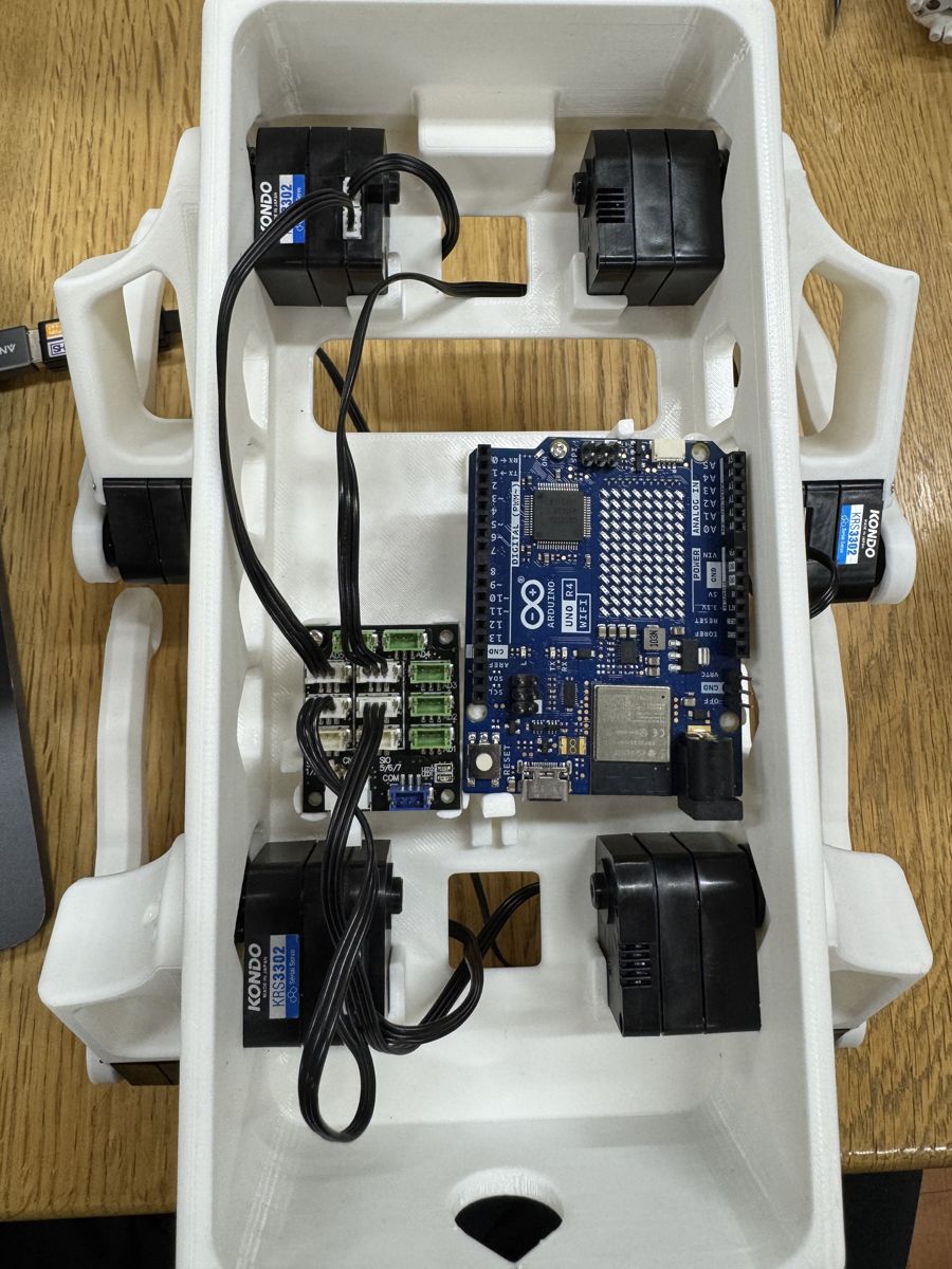
Wiring#
Parts of the RCB-4mini#
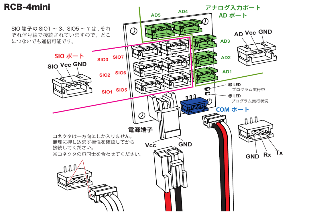
Names of the RCB-4mini’s parts (source: Kondo Kagaku, “HeartToHeart4 Instruction Manual Ver.8”, page 7)#
Port |
Use |
|---|---|
SIO1–3, SIO5–7 |
Servos connect here. Pins are SIO (signal), Vcc (battery voltage), GND |
COM |
Connects to the Arduino. Pins, from the GND side: GND, Rx, Tx |
Power terminal |
The battery connects here |
AD1–AD5 |
Not used |
Servos → RCB-4mini#
Servos connect to the SIO ports and can be daisy-chained. The RCB-4 tells the connected servos apart by their ICS number. The ICS number is determined by the servo’s ID and by which group of SIO ports it is connected to.
SIO port used |
ICS number |
Example: servo with ID 3 |
|---|---|---|
SIO1–3 |
ID × 2 |
6 |
SIO5–7 |
ID × 2 + 1 |
7 |
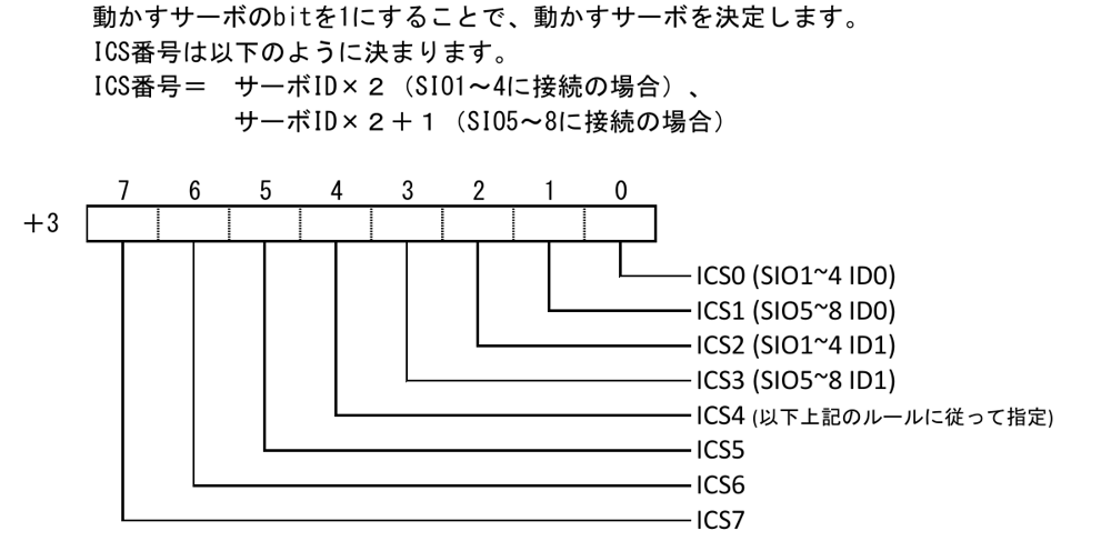
How ICS numbers are determined (source: Kondo Kagaku, “RCB-4HV Command Reference”, page 17, in the RCB-4 Reference Set Ver.2.2). The RCB-4HV has 8 SIO ports, 1–4 and 5–8; the RCB-4mini has 6, 1–3 and 5–7; the rule is the same#
The firmware checks both groups at startup, so either group works. In the startup messages, the SIO1–3 side is shown as “右” (right) and the SIO5–7 side as “左” (left).
What to connect#
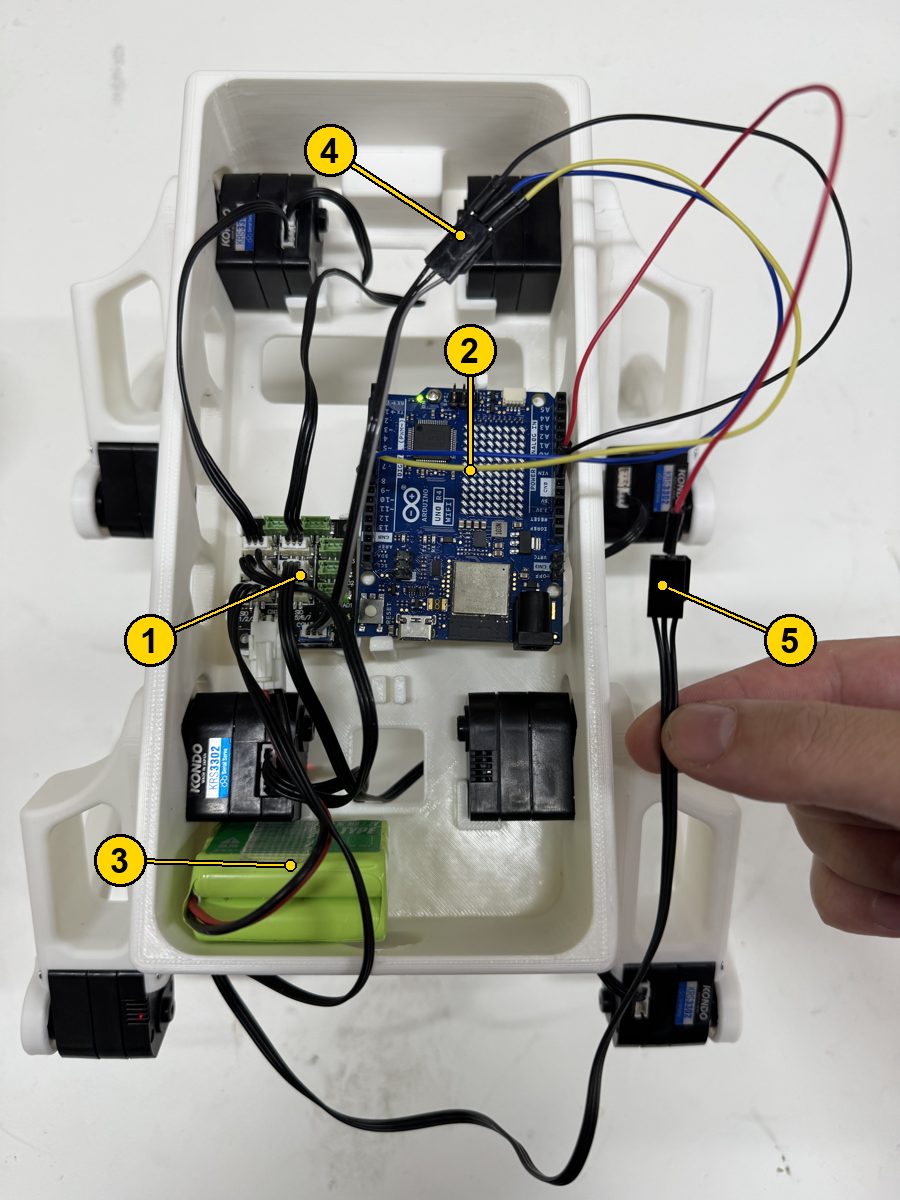
The whole wiring. The numbers match the table below#
No. |
Item |
Connects to |
|---|---|---|
1 |
RCB-4mini |
8 servos on the SIO ports, 4 on the COM port, 5 on a free SIO port, the battery on the power terminal |
2 |
Arduino UNO R4 WiFi |
4 on D8, D9 and GND; 5 on VIN |
3 |
Battery (ROBO Power Cell E type (Ni-MH 7.2 V)) or AC adapter |
The RCB-4mini’s power terminal |
4 |
ZH connection cable 2 B type + 3 jumper wires (for COM) |
RCB-4mini’s COM port → Arduino’s D8, D9, GND |
5 |
ZH connection cable 2 B type + 1 jumper wire (for power) |
Vcc of a free SIO port on the RCB-4mini → Arduino’s VIN |
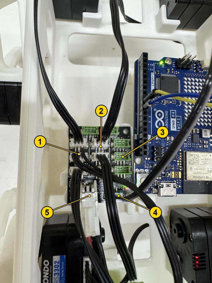
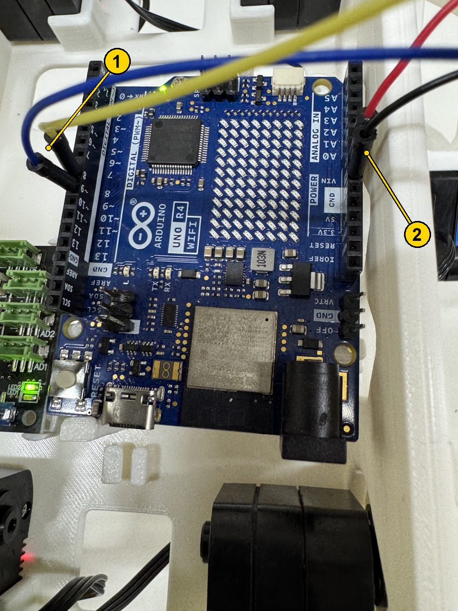
RCB-4mini COM → Arduino#
RCB-4mini COM |
Arduino UNO R4 WiFi |
|---|---|
Rx (next to GND) |
D9 |
Tx (furthest in) |
D8 |
GND |
GND |
This is the usual crossed wiring: the sending side (the Arduino’s D9) goes to the receiving side (the RCB-4’s Rx). Unlike the Feetech version’s board, it is not TX to TX and RX to RX.
Note
D0 / D1 are the Arduino’s hardware serial (Serial1) pins. The RCB-4’s COM port uses a special serial with an inverted signal (1.25 Mbps) that Serial1 cannot talk to, so the firmware drives D8 / D9 directly with a timer and DMA. D0 / D1 remain free for other devices.
Power#
There are two ways to power the robot. Both go into the RCB-4mini’s power terminal, which distributes power to the servos and the Arduino.
AC adapter |
Battery |
|
|---|---|---|
What to use |
Kondo Kagaku’s AC adapter (5.9 V 2 A), with the supplied LV conversion DC jack attached |
ROBO Power Cell E type (Ni-MH 7.2 V) (included in the KXR Advanced Set B) |
Voltage |
5.9 V |
7.2 V nominal |
Suited to |
Trying things repeatedly on the desk, without worrying about the battery running out |
Walking without a cable |
The end of the LV conversion DC jack is the same VH 2-pin connector as the battery, so it plugs straight into where the battery goes.
Connect the AC adapter or the battery to the RCB-4mini’s power terminal. Power for the servos is distributed from here through the SIO ports.
Connect Vcc of a free SIO port to the Arduino’s VIN. An SIO port’s Vcc carries the power terminal’s voltage directly. GND is already connected through the COM port’s GND. Do not connect the SIO port’s SIO (signal) pin (it is the servos’ communication line itself).
Having the USB cable plugged in at the same time is fine (see “Why VIN and USB can be connected at the same time” below). There is no need to unplug it when flashing.
Warning
The Arduino’s VIN accepts 6–24 V.
The AC adapter’s 5.9 V is slightly below that range. The Arduino’s 5 V can sag, so keep the USB cable plugged in as well when using the AC adapter. USB makes up the shortfall.
The same applies when the battery drains below 6 V. Charge it before then.
The AC adapter supplies up to 2 A. When all 8 servos push hard at once this can fall short, and Kondo Kagaku’s product page also says it may not work properly depending on the number of servos and the load of the motion. If the RCB-4mini or the Arduino resets while walking, try the battery.
Why VIN and USB can be connected at the same time#
This is an excerpt of the UNO R4 WiFi schematic (the power section).
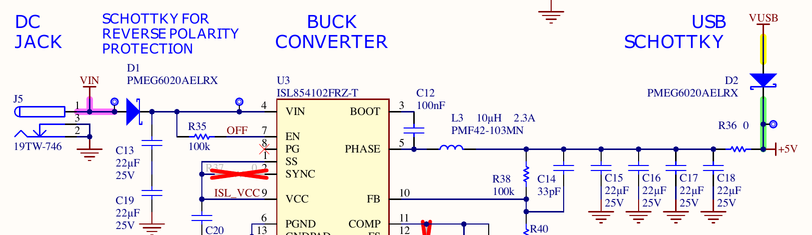
The DC JACK, BUCK CONVERTER and USB SCHOTTKY parts of the Arduino UNO R4 WiFi schematic (ABX00087). Source: Arduino SA, CC BY-SA 4.0#
The VIN pin on the header is the same VIN net as the DC jack (J5). The current paths
are as follows.
VIN pin / DC jack ──D1──> buck converter U3 ──> +5V ──> MCU, 3.3 V regulator
USB-C VBUS ─────────D2─────────────────────────> +5V
D1 and D2 are Schottky diodes (PMEG6020AELRX), which let current flow only in the direction of the arrow. +5V is fed by two supplies, each through a diode, and power comes from whichever is at the higher voltage.
When there is voltage on VIN, the buck converter U3 holds +5V at 5.0 V. The USB side can only deliver about 4.7 V after the drop across D2, so D2 is reverse-biased and no current flows from USB. No current flows from +5V back into the PC’s USB either (D2 blocks it).
On USB alone, even if +5V leaks back through U3 towards VIN, D1 stops it, so no current flows from USB towards the battery or the AC adapter either.
When VIN drops below 6 V, U3 can no longer hold 5 V, but with USB plugged in, USB makes up through D2 for whatever +5V drops below the USB side’s roughly 4.7 V. This is why the warning above says to keep USB plugged in when using the AC adapter.
Wiring underneath#
The knee servos’ cables run under the body and into it. After closing the lid, check from below that everything looks like this.
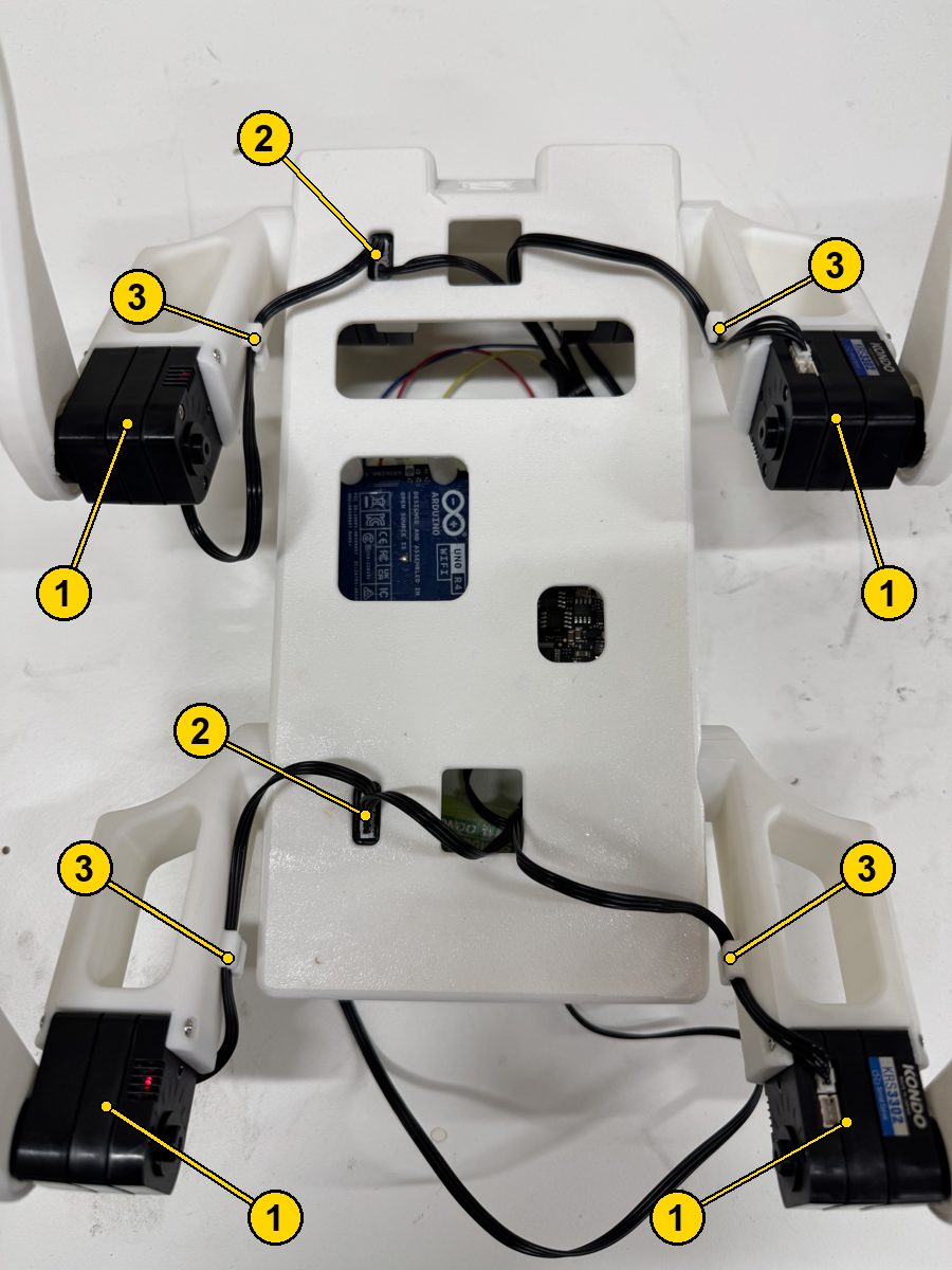
Seen from below. 1: knee servos (4), 2: holes where the cables go into the body, 3: where the cables are fixed along the legs#
Keep the cables along the legs at the fixing points (3) so they are not pulled or pinched when the legs move.
Flash and calibrate#
From here on, the flow is the same as Learning to walk (reinforcement learning). The only differences are the env you flash and the file you write the calibration values into.
Flash. Before calibration, the firmware only reads the servo angles and does not send target angles.
$ uv run pio run -d 13_quadruped -e uno_r4_wifi_rcb4 -t upload
At startup, the serial monitor shows which joint’s servo was found at which RCB-4 number. Check that it says
サーボ応答: 8 / 8(servos responding: 8 / 8).FL_hip id 3 -> 右 #6 FL_knee id 4 -> 右 #8 ... サーボ応答: 8 / 8
Make it limp. Sending
freereleases the torque on every joint.Measure the zero points. Hang the robot up, stretch all four legs straight down and send
raw. It prints each joint’s pulse (centre is 7500); write those intoQUAD_RCB4_ZEROininclude/quad_calib_rcb4.h.Check the directions. Move only the hip to swing the foot backwards and see whether the
rawvalue goes up or down. Check the knee the same way. For a joint whose value went down from the zero point, setQUAD_RCB4_SIGNto-1(the left legs should come out as-1and the right legs as+1).Set
QUAD_RCB4_CALIBRATEDto1and flash again. Right after startup it moves to the standing pose over 2 seconds, so keep the robot hung up.Still hung up, send
rl 0.06 0; if the four legs step in alternation, you are done. Only after that, put it down on the floor and let it walk.
Walking it from the keyboard (quad_host.py serial) and the WiFi version
(-e uno_r4_wifi_rcb4_udp) are described in
code/13_quadruped/README.md.
Walking policy for the KRS version#
The KRS version has its own walking policy, trained separately from the Feetech version. The KRS-3302’s torque is 0.54–0.66 N·m (at 5.9–7.4 V supply), less than a quarter of the Feetech version’s STS3215 (2.94 N·m). So the robot model, joint range (±135°) and mass (measured 610.8 g) were all set to the KRS version and the policy was trained from scratch. Its observations include the IMU (the body’s angular velocity and the direction of gravity).
Try it in the browser#
The same simulation as Learning to walk (reinforcement learning), running the KRS version’s robot and policy. Press Walk and it walks according to the Forward and Turn commands.
Open the KRS version's simulation ↗
Results in simulation (64 robots × 10 seconds):
Command |
Measured |
Body tilt (99th percentile) |
|---|---|---|
Forward 0.04 m/s |
0.040 m/s |
4.1° |
Forward 0.08 m/s |
0.083 m/s |
3.1° |
Forward 0.12 m/s |
0.122 m/s |
3.7° |
Backward 0.06 m/s |
0.055 m/s |
5.4° |
Turn 0.4 rad/s (forward 0.08 m/s) |
0.066 rad/s |
4.2° |
It trots, with diagonal pairs of legs touching down in turn; all four legs take 3.2–3.9 steps per second.
The body and knees do not touch the floor. There is almost no time with all four feet in the air (0.1 % or less).
The joints keep at least 32° of margin against ±135°. Torque is at most 0.33 N·m at the 99th percentile (about 50 % of the maximum torque).
Turning is a weak point. With no abduction joint, it can only turn by taking different stride lengths on the left and right, so it turns only about 20 % of the commanded rate.
Flashing#
cd code
uv run pio run -d 13_quadruped -e uno_r4_wifi_rcb4_krs -t upload       # USB serial
uv run pio run -d 13_quadruped -e uno_r4_wifi_rcb4_udp_krs -t upload   # WiFi
The policy is include/krs_quad_policy.h. It does not get mixed up with the Feetech
version’s arduino_quad_policy.h. The home pose is hip +53.9° and knee −89.3° (the
underside of the body 0.13 m above the floor), which differs from the Feetech version.
Warning
An IMU is required. The IMU values are passed to the policy in body coordinates (x
forward, y left, z up; gravity is (0, 0, −1) when level and at rest). If the sensor
board is mounted in a different orientation from the Feetech version, adjust the
rotation from the chip to the body in src/quad_imu.cpp to fit the KRS body.
Of the values used in training, the following are assumptions that were not measured:
The servo position-loop gains (kp 5.5 N·m/rad, kd 0.11). Training randomised them by 0.5–2×
The delay before a command arrives (20–40 ms)
The battery position and the mass of the Arduino UNO R4 WiFi (25 g)
How it was trained is in the “KRS 版” (KRS version) section of
code/13_quadruped/rl/README.md.
Troubleshooting#
Symptom |
Check |
|---|---|
|
The adapter’s LED is red (ICS mode). Only one servo is connected. On macOS, libusb; on Linux, the |
Some joints show |
Check that servo’s ID and |
Only one leg moves backwards |
That servo’s |
A joint keeps turning without stopping |
That servo’s |
A joint bends only part of the way |
The horn is not fitted far off. Start again from “Centre the servo before fitting the horn and leg” above |
The Arduino resets while walking |
The battery voltage: has it dropped below 6 V? With the AC adapter, is the USB cable also plugged in, and does it help to switch to the battery? |
About the project written to the RCB-4mini
The RCB-4mini only talks to the servos “assigned” in a project written with Kondo Kagaku’s Heart to Heart 4. The firmware assigns the servos of any joints it cannot find by itself at startup, so there is no need to recreate the project in Heart to Heart 4 (it only writes to the RCB-4mini’s RAM and does not change the project stored inside).
Sources#
RCB-4mini supply voltage (6–12 V): https://kondo-robot.com/product/rcb4_mini
Diagram of the RCB-4mini’s parts (SIO / AD / COM / power terminal, pin order): Kondo Kagaku, “HeartToHeart4 Instruction Manual Ver.8”, pages 6–7 https://www.kondokagaku.jp/data_download/HeartToHeart4_manual_Ver8_JP.pdf
Diagram of how ICS numbers are determined, ICS assignment table (RAM
$0044): Kondo Kagaku, “RCB-4HV Command Reference”, page 17, and “RCB-4HV Firmware Reference” (in the RCB-4 Reference Set Ver.2.2) https://kondo-robot.com/faq/rcb-4-reference-ver-2_2Dual USB Adapter HS (red LED is ICS, green is serial): https://kondo-robot.com/product/02116
ICS3.5/3.6 Manager (Windows): https://kondo-robot.com/faq/ics35mag, usage https://kondo-robot.com/faq/how-to-use_ics3-5-manager
KRS-3302 operating angle of 270 degrees (±135 degrees): https://kondo-robot.com/product/03146, KRS series instruction manual V2.1 https://kondo-robot.com/w/wp-content/uploads/KRS-series_manual_Download-V2_1.pdf
Position values 3500–11500 (centre 7500): ICS3.5/3.6 Software Manual v2.9 https://kondo-robot.com/w/wp-content/uploads/ICS3.5_3.6_SoftwareManual_2_9.pdf
ID of a new KRS servo (0): KRS series instruction manual V2.1 (same as above)
ROBO Power Cell E type (Ni-MH 6 cells, 7.2 V nominal, 800 mAh, VH 2-pin): https://kondo-robot.com/product/02335
Arduino UNO R4 WiFi VIN (6–24 V), VUSB (4.8–5.5 V), about 4.7 V when powered from USB, part numbers of D1 and D2: https://docs.arduino.cc/resources/datasheets/ABX00087-datasheet.pdf (section 2 “Recommended Operating Conditions”, section 11 “Power Options”)
Arduino UNO R4 WiFi schematic (source of the power section figure, CC BY-SA 4.0): https://docs.arduino.cc/resources/schematics/ABX00087-schematics.pdf
AC adapter (5.9 V 2 A, part number 04052, LV conversion DC jack included, the caution that it may not work properly depending on the number of servos and the load): https://kondo-robot.com/product/04052
LV conversion DC jack (VH 2-pin ⇔ DC plug 5.5 × 2.1 mm): https://kondo-robot.com/product/02186
Horn screws (the KRS-3300 series comes with M3-6 low-head horn screws), screws for the horn, 2.6-4 flat head screws only on the free-horn side: KRS series instruction manual V2.1, page 10, “Attaching the servo horn” (same as above)
Lengths of the frame mounting screws (2-4 + frame thickness, effective pilot-hole depth of 4.8mm in the upper case, case screws 2-20 low-head tapping screws for the bottom case): Kondo Kagaku, “Frame mounting screw reference drawing, KRS-3300 series” https://kondo-robot.com/w/wp-content/uploads/KRS-3300_Frame-BISS-A4-0809.pdf (from https://kondo-robot.com/faq/krs-3300dimention)
2mm screws for the upper case; the bottom case is clamped together after removing the case screws: https://kondo-robot.com/product/03146
Small-diameter horn B (PCD φ12, M2): https://kondo-robot.com/product/02157
Contents of Screw Set A (for KXR): https://kondo-robot.com/product/02328
Case screw set for the KRS-3300 series (2-20 tapping screws): https://kondo-robot.com/product/02183
Plate thicknesses, the thickness of the horn’s screw holes, and the engagement of the case screws and the M3 horn screws were measured in the KRS version’s CAD (SolidWorks)
ics-manager’s screen and key bindings:rcb4/ics.pyiory/rcb4. Thevkey for reverse mode was added in iory/rcb4#232 and is in rcb4 0.1.4 on PyPI https://pypi.org/project/rcb4/0.1.4/