Assembly — 8-DoF quadruped#
First build the three kinds of units (the body with its servos, the left legs and the right legs), then attach the legs to the body.
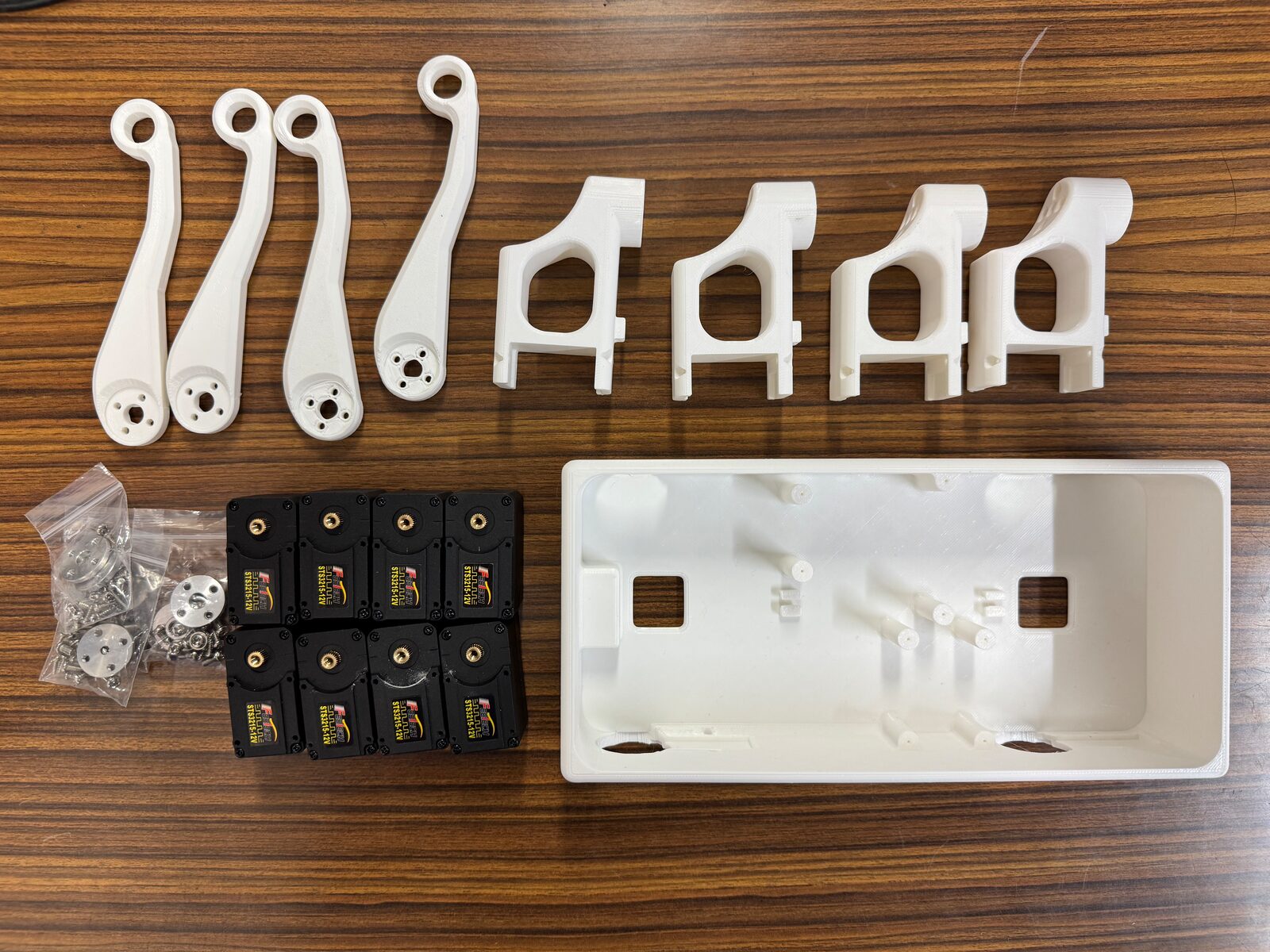
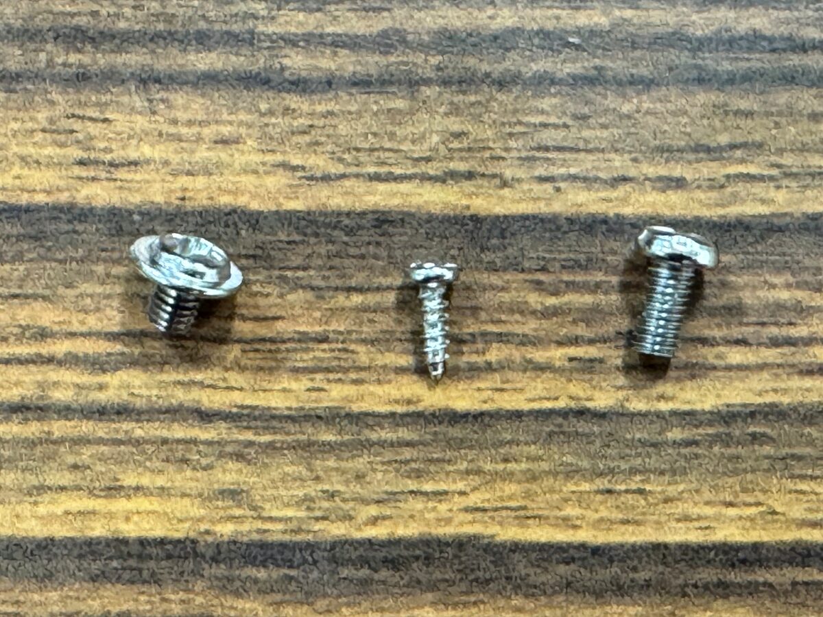
You need 40 M3×6 screws and 16 M2×6 screws, and the screws that come with the STS3215 servos are enough (eight servos include plenty). Nothing else to buy.
The step images below are CAD renders whose labels are in Japanese; the steps are spelled out in English next to each one.
Interactive 3D viewer#
Plays the assembly step by step as an animation in the browser. Drag to rotate the view and use the slider to step back and forth.
Units#
The robot is built from three kinds of units (sub-assemblies) first; the legs go on the body last. There are 81 individual parts (8 kinds) in total.
Unit |
Qty |
Parts inside |
|---|---|---|
body_servo (body + 4 servos) |
×1 |
13 |
leg_left (left leg) |
×2 |
11 |
leg_right (right leg) |
×2 |
11 |
Part |
Qty |
|---|---|
Screw M3×6 |
×40 |
Screw M2×6 |
×16 |
STS3215 (case + horn: the part on the servo shaft that turns with it) |
×8 |
bracket_outline |
×4 |
leg_link1 |
×4 |
Body |
×1 |
Give each servo an ID#
Before building the units, give the eight servos the IDs 1 to 8. All eight share one bus, and the microcontroller addresses each servo by its ID. New STS3215 servos, however, all ship as ID 1, so out of the box they cannot be told apart.
Set the IDs with one servo connected at a time. With two ID-1 servos on the bus, a “change ID 1 to 2” command reaches both of them and both become ID 2. The tool still sees what looks like one servo, so nothing tells you it went wrong.
What you need#
A PC (Windows / macOS / Linux)
The driver board (Waveshare Bus Servo Adapter (A)) and a USB Type-C cable
The 12 V AC adapter (item 3 in the parts list)
An STS3215 (just one to start with)
Masking tape and a pen, for number labels
Install the tool#
IDs are set with feetech-cli. With the uv you
installed while setting up (if you have not yet, see “Install uv” for
macOS / Windows /
Linux first), one line installs the feetech command:
$ uv tool install feetech-cli
uv takes care of Python, so there is nothing else to install. The command goes into
the same place as uv itself, so any shell where uv runs also finds feetech.
Connect#
Put both jumpers on B (USB-SERVO). A is the position for driving the servos from an Arduino; left on A, the PC cannot see the servo.
Plug a single servo into one of the board’s 3-pin connectors (D V G).
Plug the AC adapter into the board’s DC jack. The servo cannot be powered from USB, so without this it does not answer.
Connect the board to the PC with the USB Type-C cable.
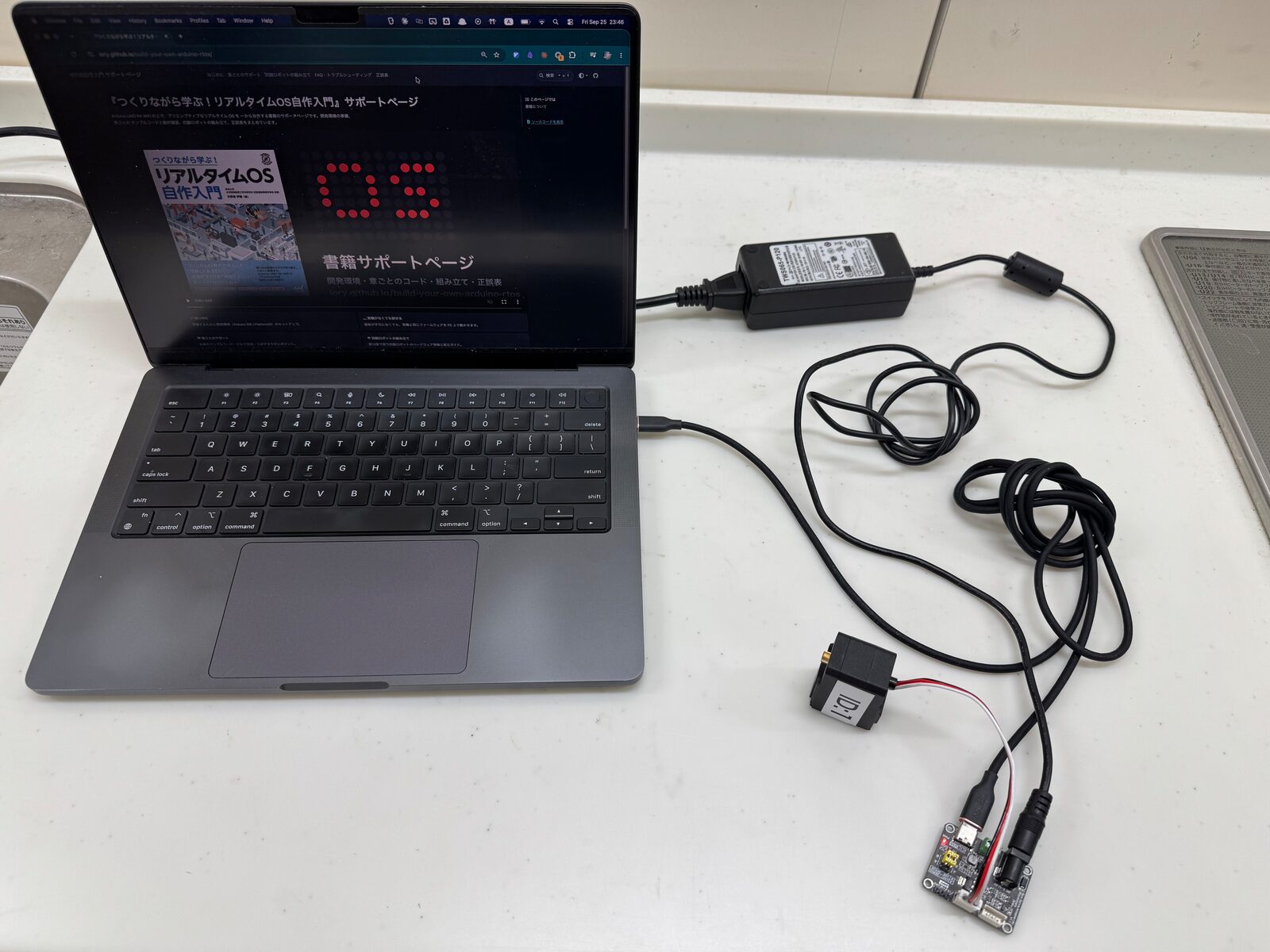
The whole setup. PC to board over USB Type-C, board powered from the AC adapter, exactly one servo#
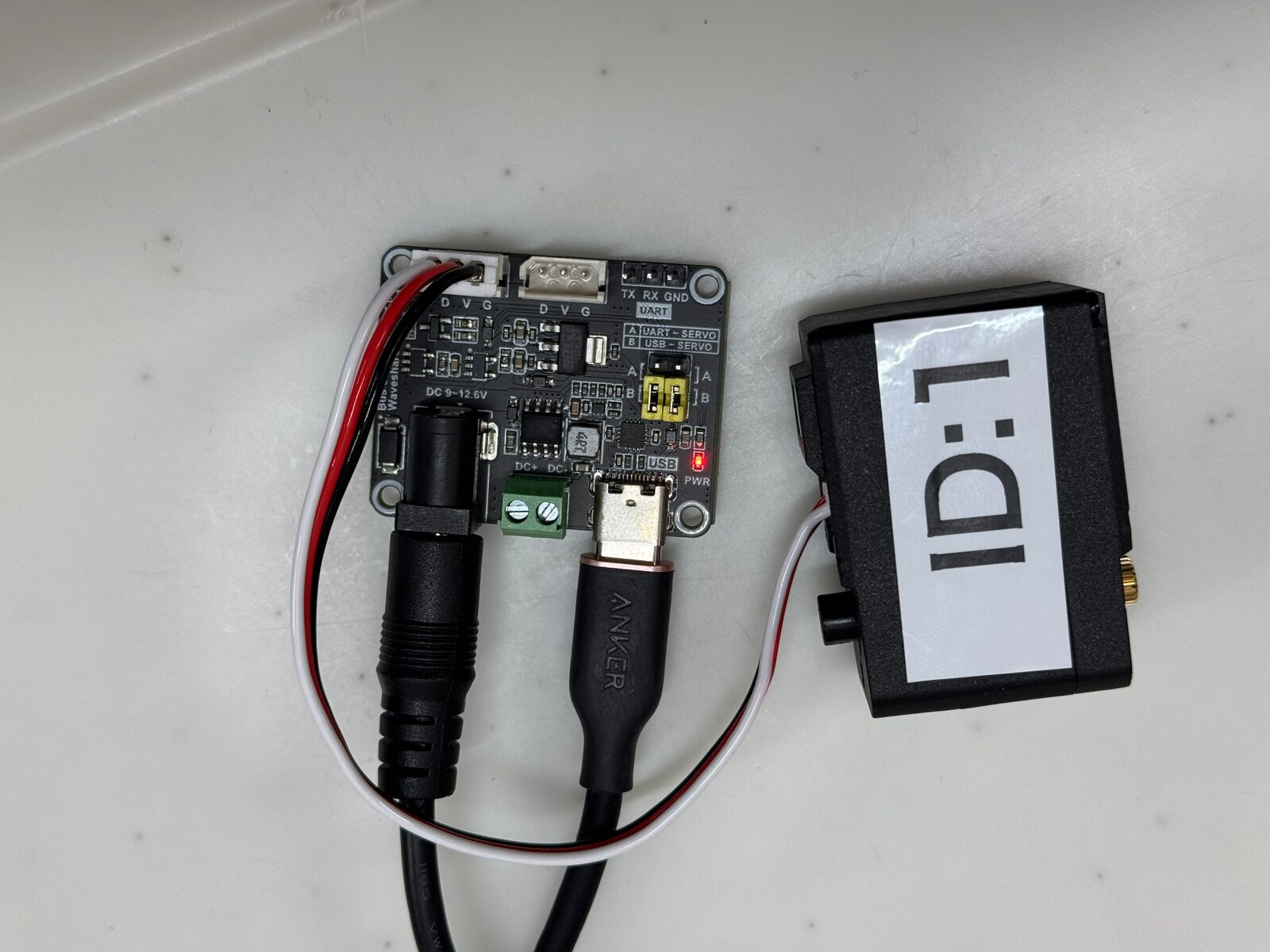
At the board: DC jack (power) on the left, USB Type-C (PC) next to it, and the servo cable in a 3-pin connector at the top. The PWR LED lights red when power is on#
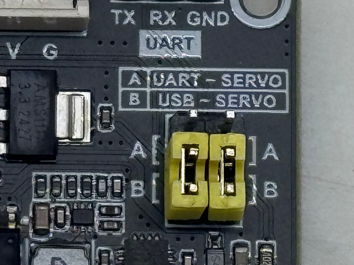
Both jumpers on B (USB-SERVO). What A and B mean is printed on the board#
Number them one by one#
Check the servo is visible.
$ feetech scan
Found 1 servo(s) on /dev/cu.usbmodem59710813431 at 1.00Mbps:
  id   1  model   777  position  4095 (+179.9 deg)  12.3V  32C
A single
id 1line means you are ready. The port name depends on your system (COM3or similar on Windows); the tool finds it by itself, so there is nothing to pass.Write the new ID. It is written once you answer
y. The first servo can keep ID 1, so this step starts with the second one.$ feetech set-id 1 2 Change servo 1 to id 2? This writes the servo EEPROM. [y/N] y Servo 1 is now id 2.
The ID is stored in the servo’s EEPROM, so it survives a power cycle.
Run
feetech scanagain and check the servo answers at its new ID.Label the servo. Once they are mixed up, the only way to tell them apart is to connect them one by one again. A label on a face that stays visible after assembly also helps later, when wiring or replacing a servo.
Unplug it, connect the next new servo and go back to step 1. The third one gets
feetech set-id 1 3, the fourthfeetech set-id 1 4, and so on up to 8.

Steps 1 to 3 on real hardware#
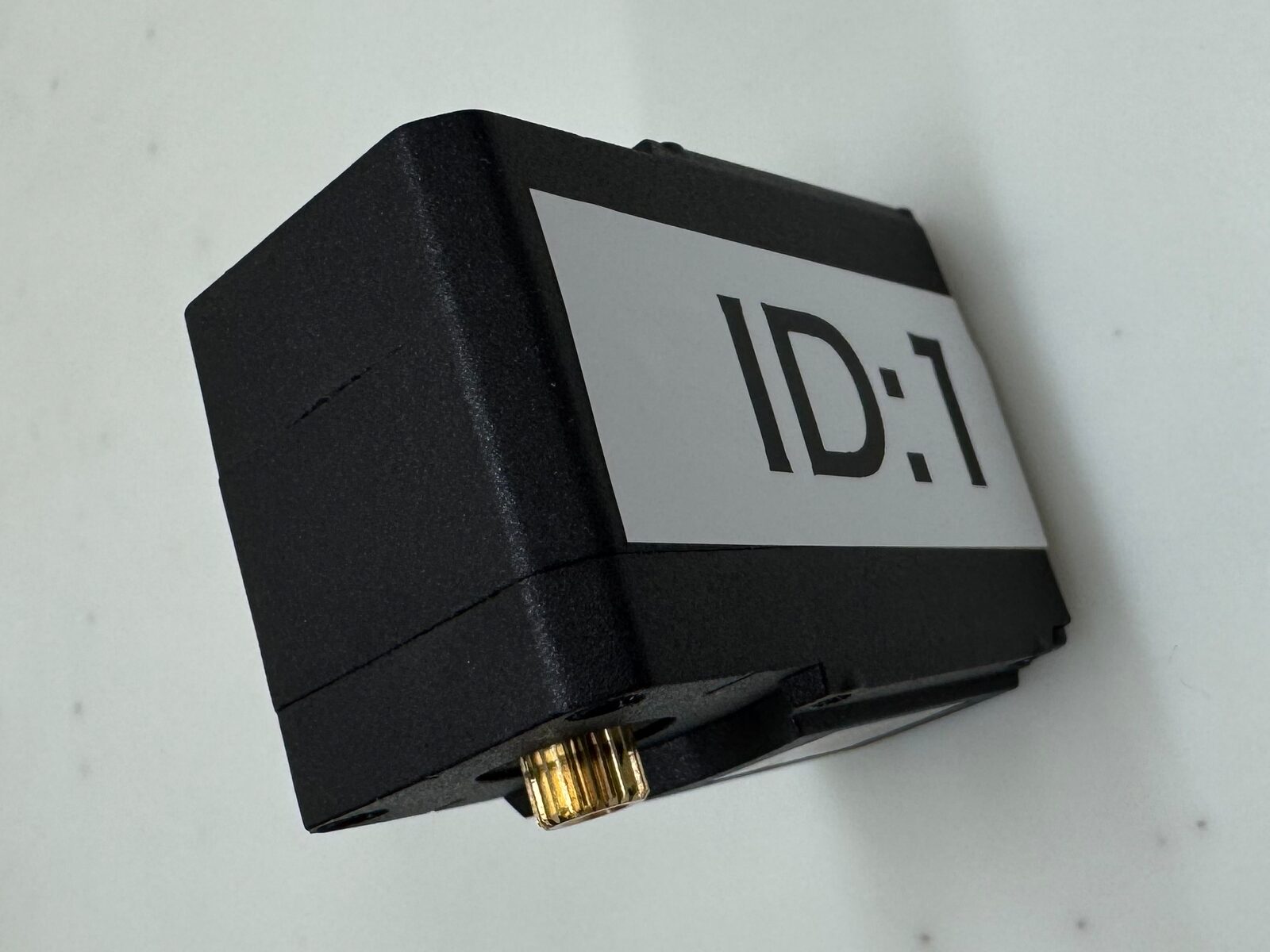
A servo with its number label#
Which servo goes where#
Each ID belongs to one joint of one leg. The assignment is the one in the firmware’s
include/quad_calib.h (QUAD_SERVO_ID), so mount the servos exactly as shown. A
servo in the wrong place receives another joint’s commands.

Servo ID assignment. Seen from above, the front (the walking direction) is the end with the tab in the middle of the body’s short side#
Use these servos when building the units below.
Unit |
Servos inside |
IDs to use |
|---|---|---|
body_servo (body) |
the hips of all four legs |
1 (front right), 3 (front left), 5 (rear right), 7 (rear left) |
leg_right (right leg) ×2 |
the knees of the right legs |
2 (front right), 6 (rear right) |
leg_left (left leg) ×2 |
the knees of the left legs |
4 (front left), 8 (rear left) |
Troubleshooting#
Symptom |
Check |
|---|---|
|
The AC adapter is plugged in (PWR LED), the jumpers are on B, the servo cable is fully seated |
No port is found |
The USB cable carries data (a charge-only cable shows no port) |
A servo whose bus speed was changed before is not found |
|
|
A servo with that ID is also connected. Leave only one and try again |
Building the units#
Each kind of unit is shown once; ×N is how many the whole robot uses. Build them from top to bottom and you will have every unit you need. In the steps, “coaxial φ◯ mm” means lining up the centres of the holes, and “mating faces” means pressing two faces flat against each other.
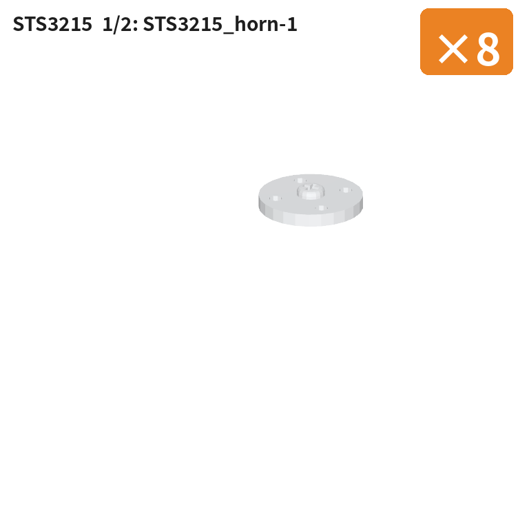
STS3215 servo (fitting the horn) ×8
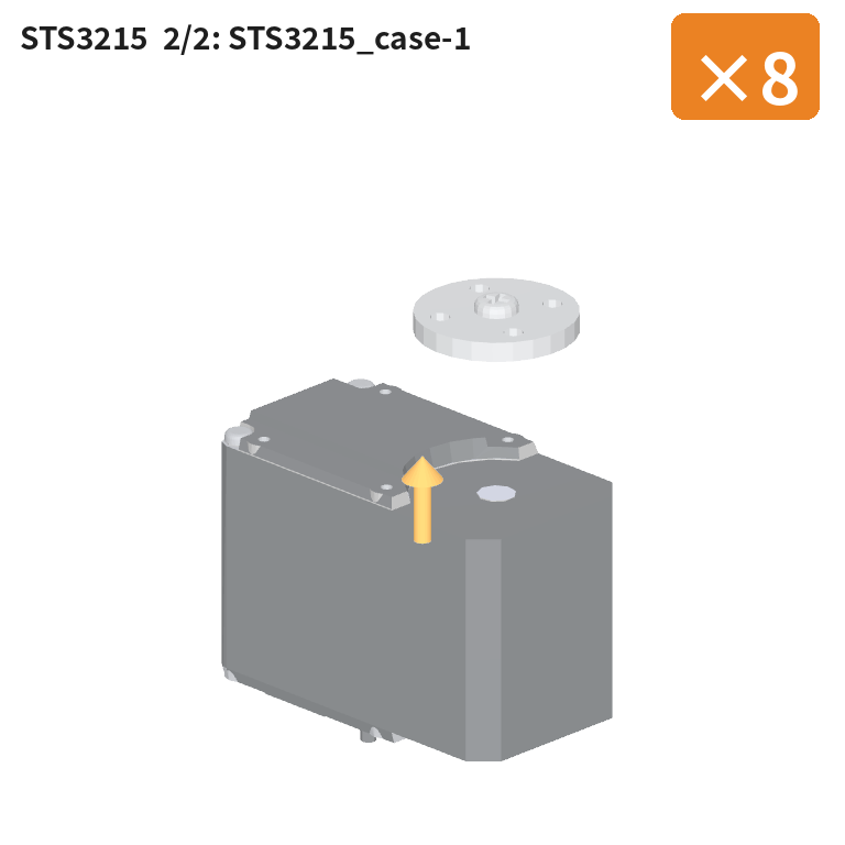
Only if the horn arrived detached. If it is already fitted, skip this unit.
Place the STS3215_horn (base).
STS3215_case onto the horn — coaxial φ4.8 mm (×2), 2 mating faces.
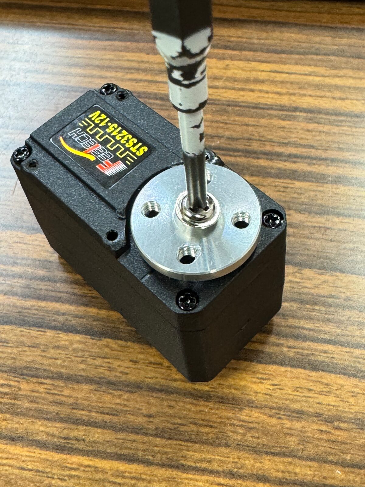
Hold the screwdriver tip in line with the screw hole. If the tip is at an angle the force does not get through and the screw head strips easily#
body_servo (fixing 4 servos in the body) ×1
Parts: body ×1, STS3215 ×4, M3x6 ×8
STS3215-1 to -4 below are the CAD part numbers, not servo IDs. The four positions in the body take the hip servos (IDs 1, 3, 5, 7); match each position to its ID with the ID assignment figure.
Place the body (base).
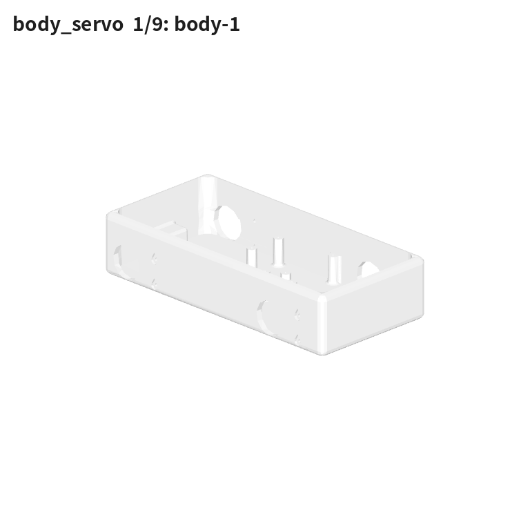
STS3215-4 — insert into the body (coaxial φ4.2 mm ×4, 2 mating faces).
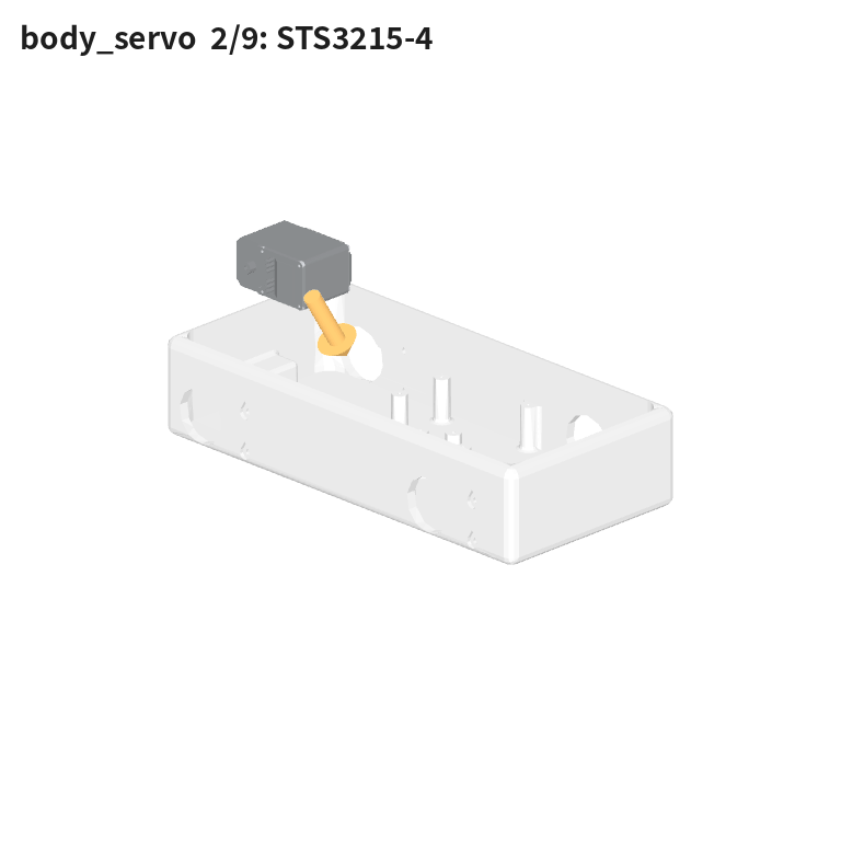
🔩 Tighten M3x6 ×2 (STS3215-4 ↔ body).
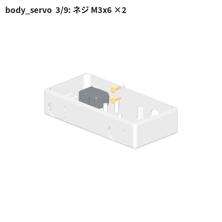
STS3215-3 — insert into the body.
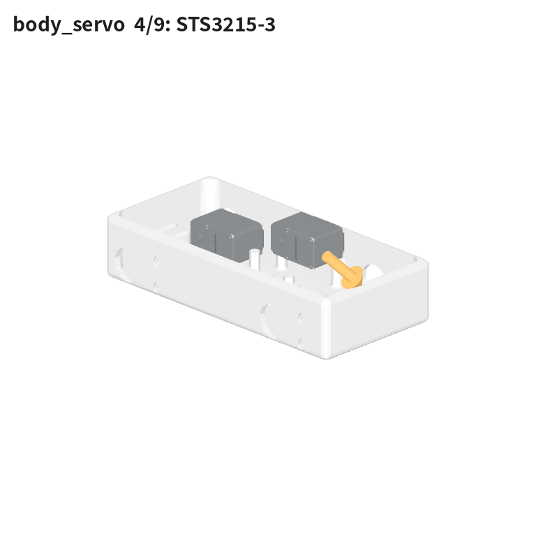
🔩 Tighten M3x6 ×2.
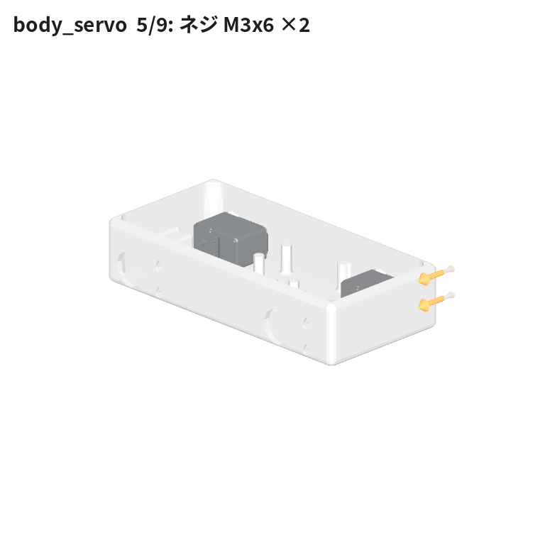
STS3215-2 — fit to the body (2 mating faces).
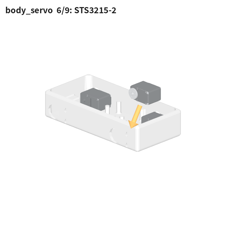
🔩 Tighten M3x6 ×2.
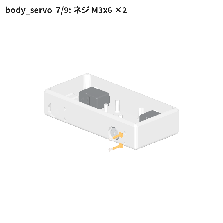
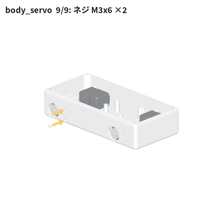
STS3215-1 — fit to the body (2 mating faces).
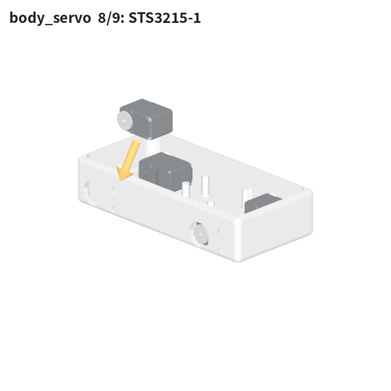
🔩 Tighten M3x6 ×2.
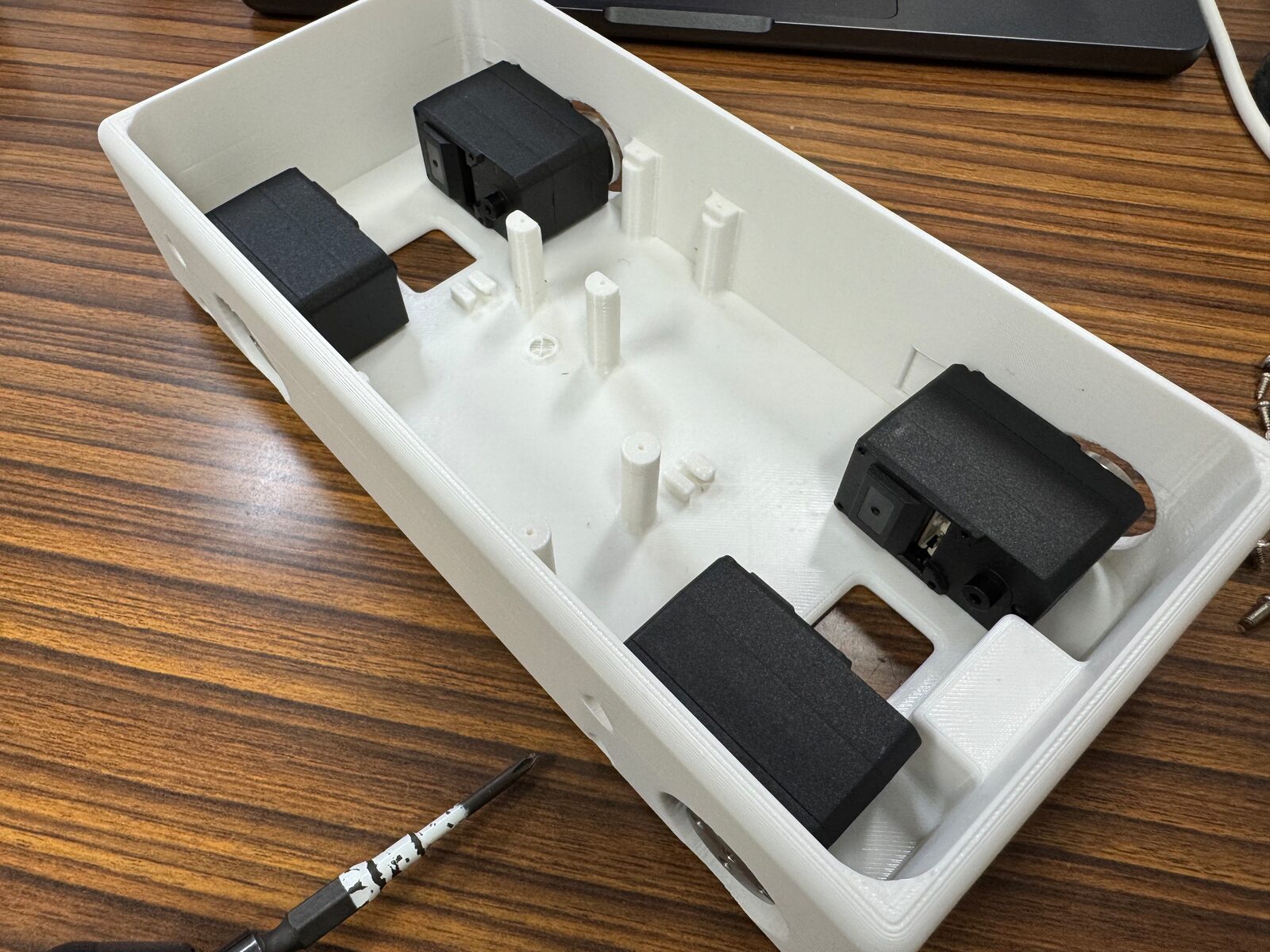
The body with its four servos fixed (the real thing)#
leg_left (left leg) ×2
Parts: STS3215 ×1, bracket_outline ×1, leg_link1 ×1, M3x6 ×4, M2x6 ×4
Place the STS3215 (base).
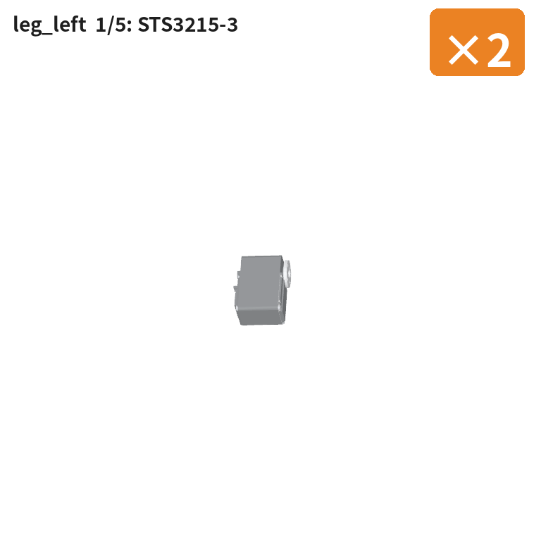
bracket_outline — insert on the horn side of the servo (coaxial φ3.2 mm ×4, 2 mating faces).
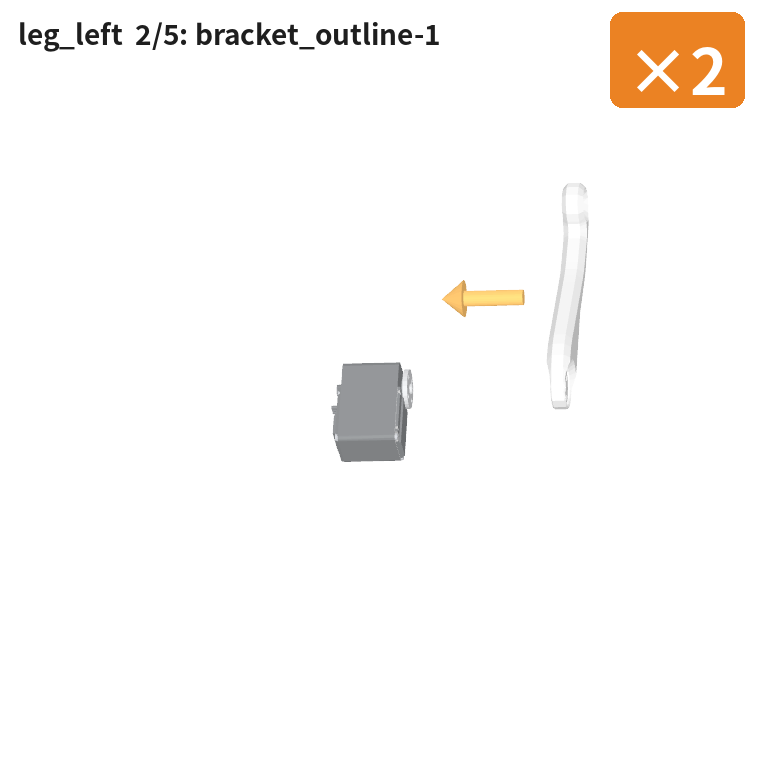
🔩 Tighten M3x6 ×4 (servo ↔ bracket).
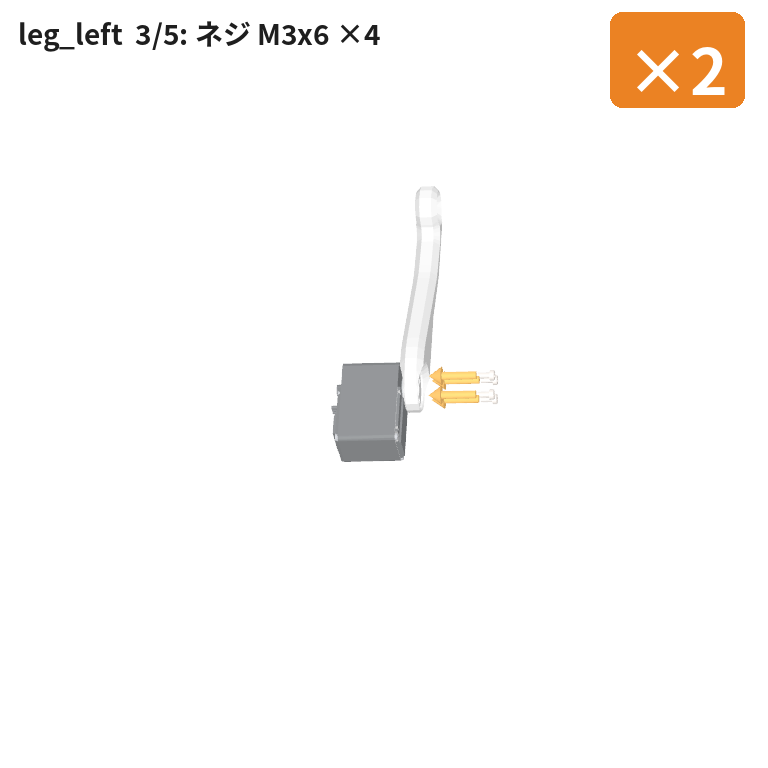
leg_link1 — insert on the case side of the servo (coaxial φ2.0 mm ×4, 2 mating faces).
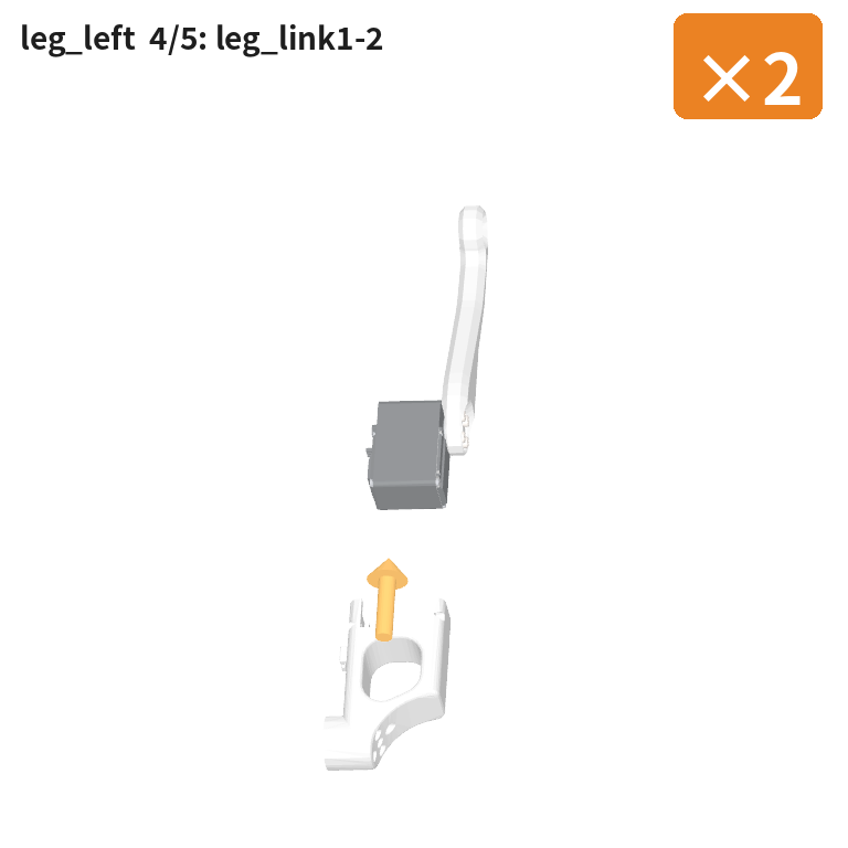
🔩 Tighten M2x6 ×4 (servo ↔ link).
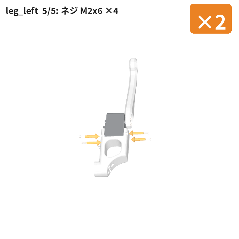
Photos of the real thing (the steps are the same for left and right legs):
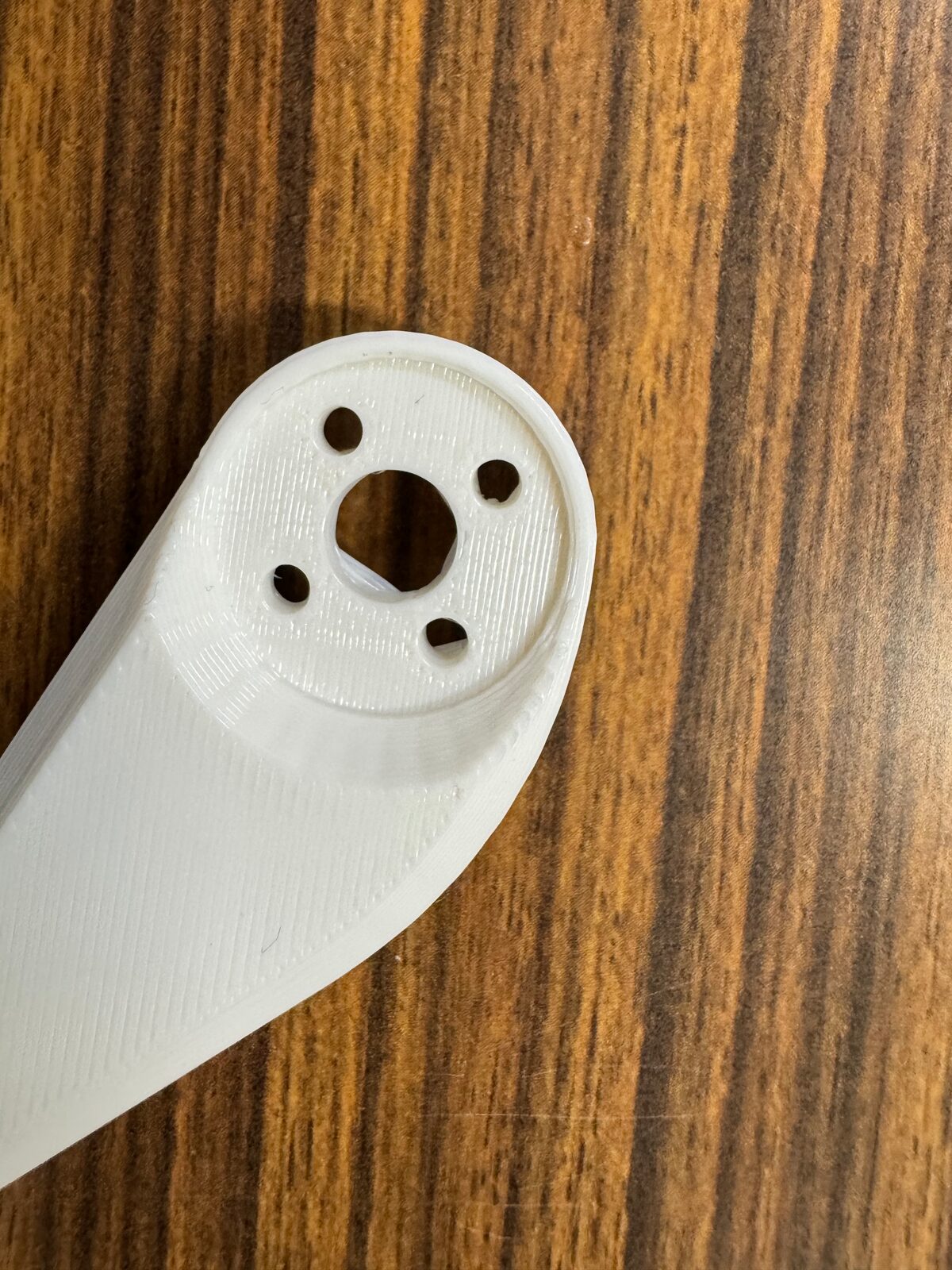
Where the leg bracket meets the horn#
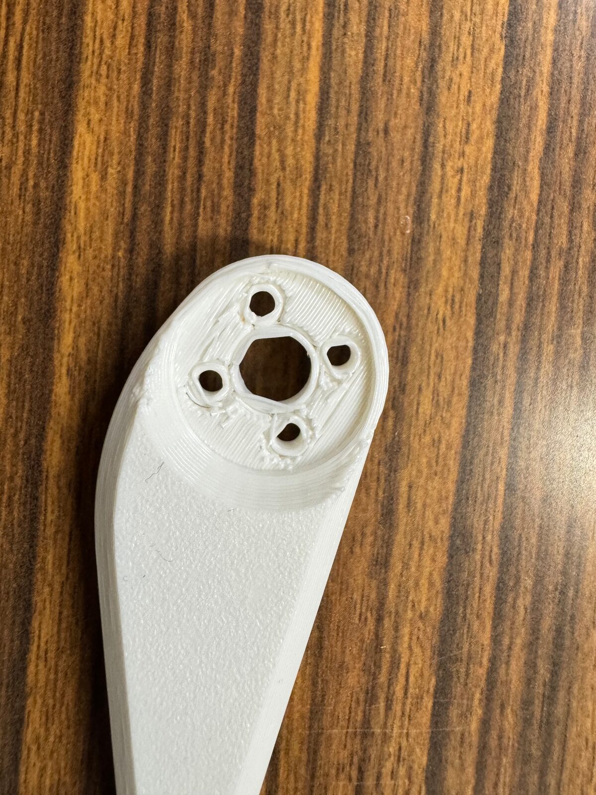
The same part from another angle#
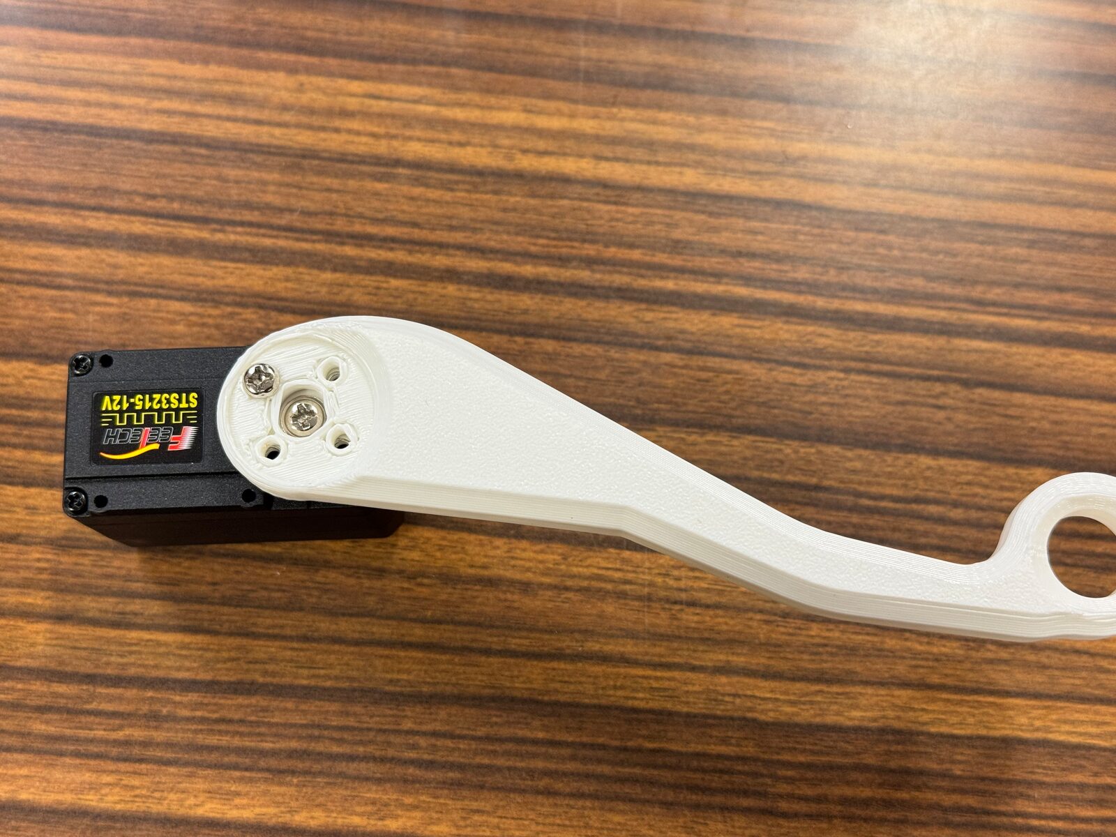
Step 2: the bracket onto the horn side of the servo#
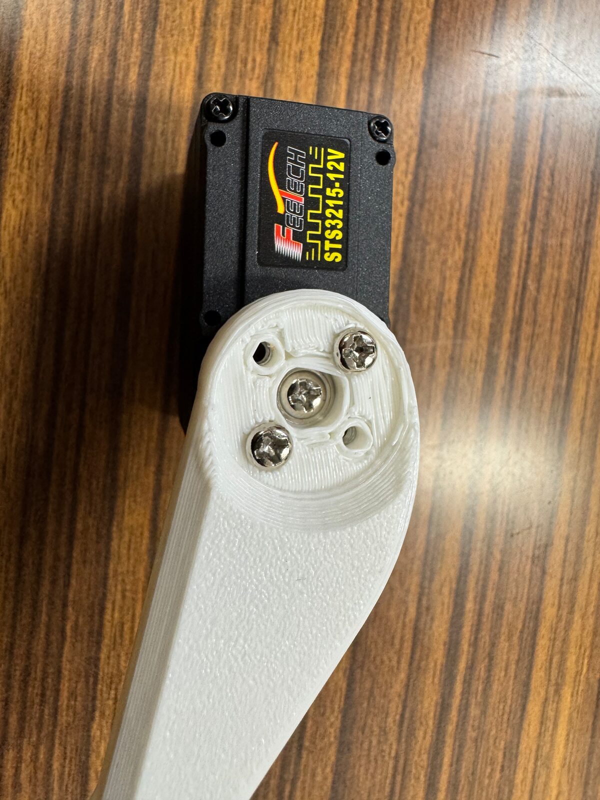
Step 3: tightening the screws#
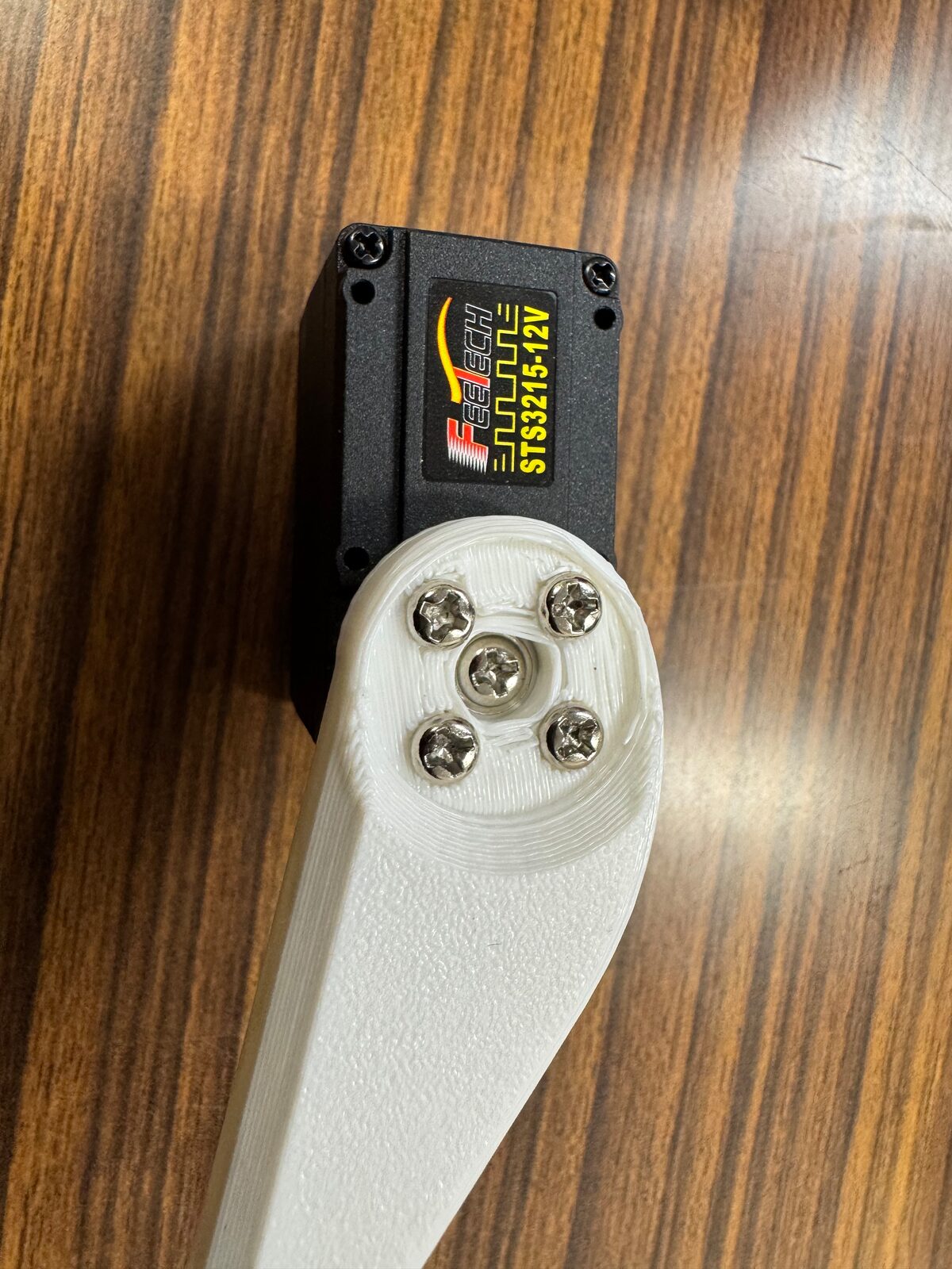
Step 3: all four M3x6 screws tightened#
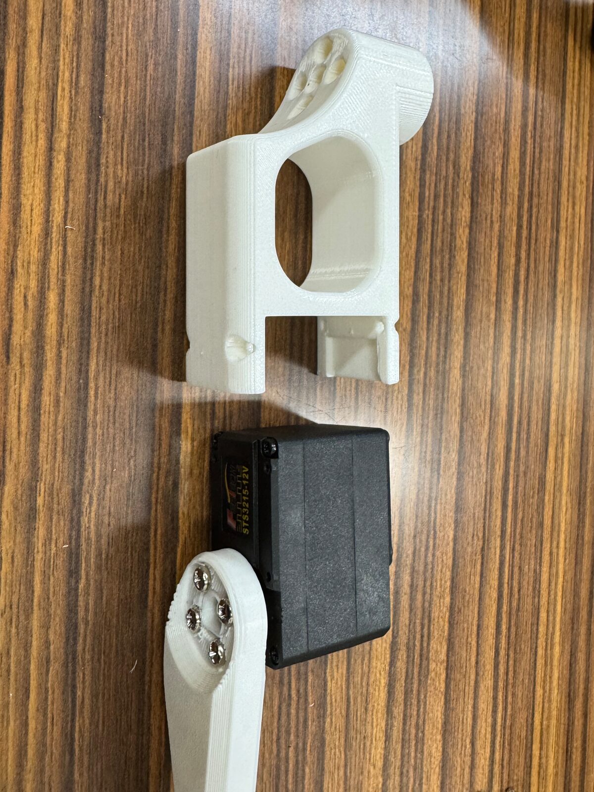
Step 4: the leg link onto the case side of the servo#
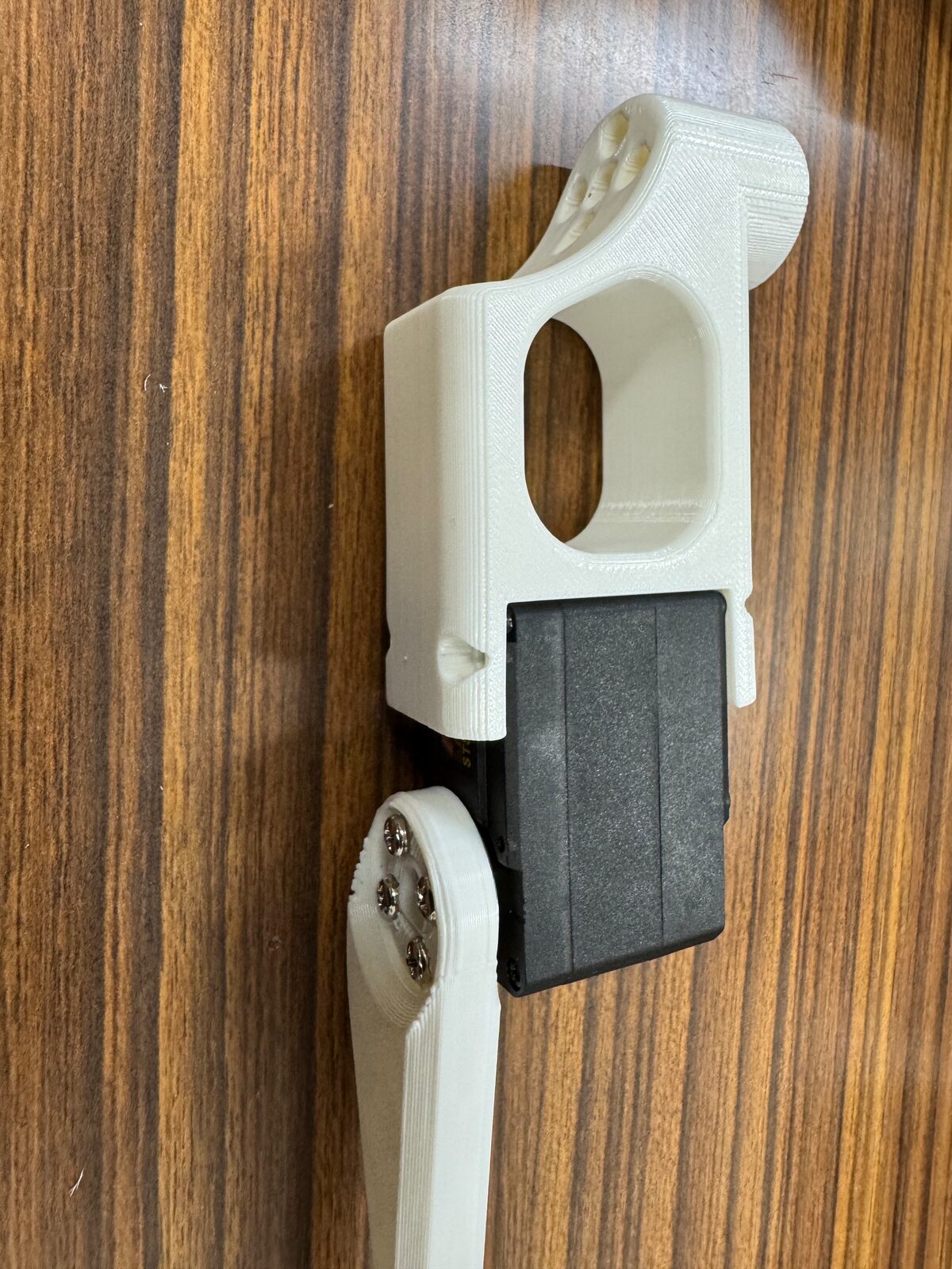
Step 4: inserted#
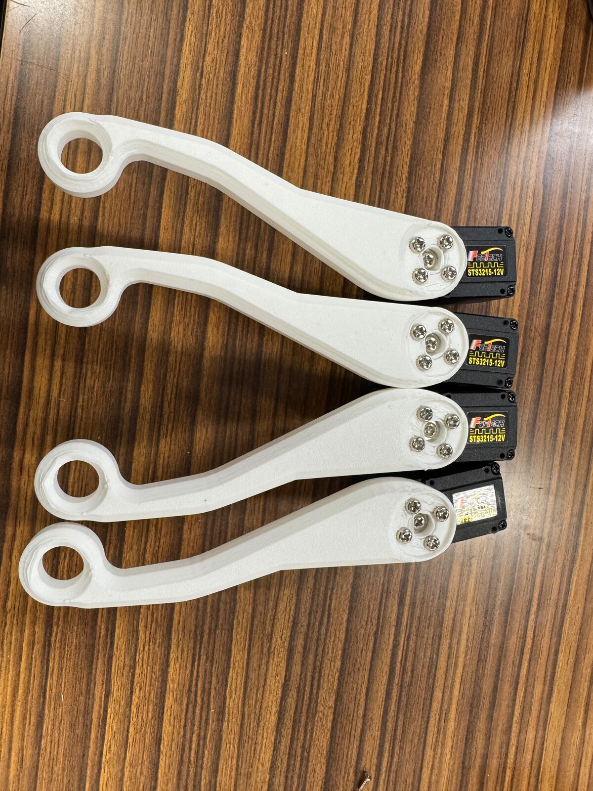
Four servos with their brackets (two left, two right)#
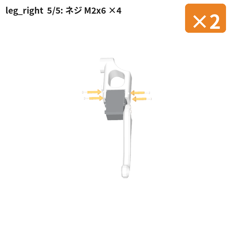
leg_right (right leg) ×2
Parts: STS3215 ×1, bracket_outline ×1, leg_link1 ×1, M3x6 ×4, M2x6 ×4 (same as the left leg, with the bracket mirrored)
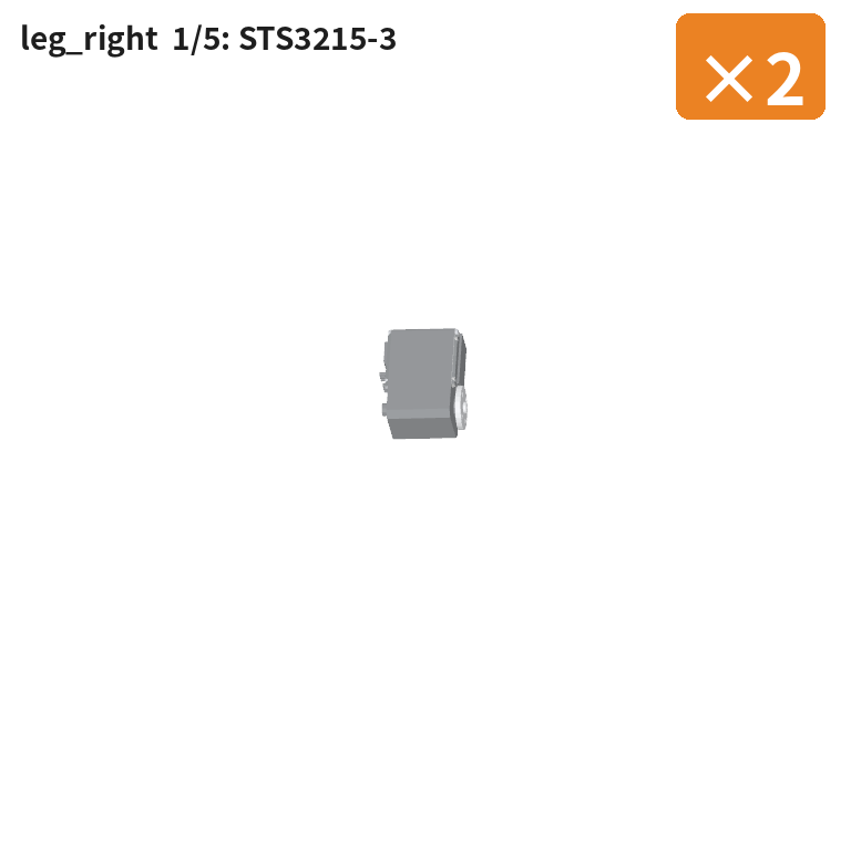
Place the STS3215 (base).
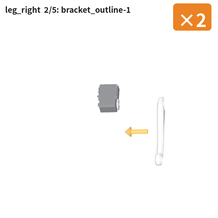
bracket_outline — insert on the horn side of the servo.
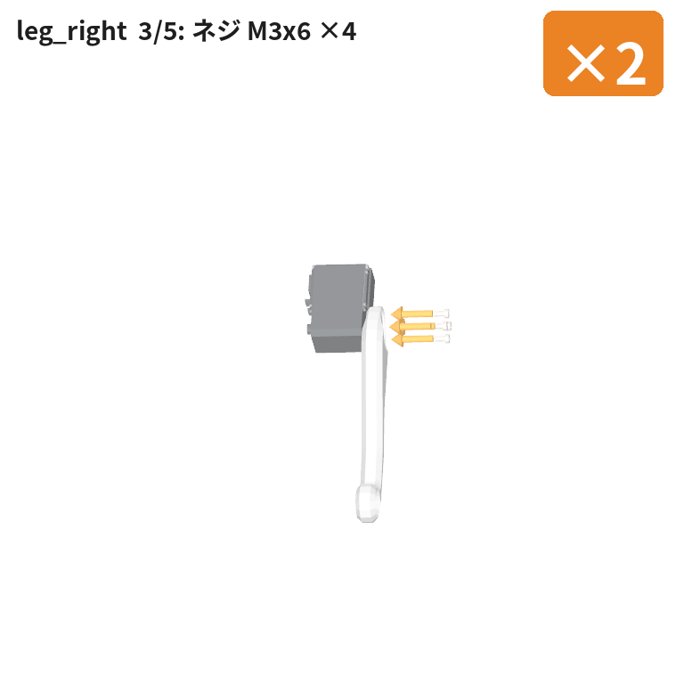
🔩 Tighten M3x6 ×4.
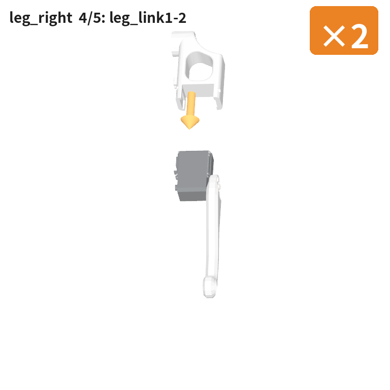
leg_link1 — insert on the case side of the servo.
🔩 Tighten M2x6 ×4.
Warning
Before you start, give every servo its ID (Give each servo an ID). Once they are in the robot you cannot tell them apart.
The zero point is set in software after assembly, so the horn angle does not matter while you build. See chapter 13 for the procedure.
Final assembly#
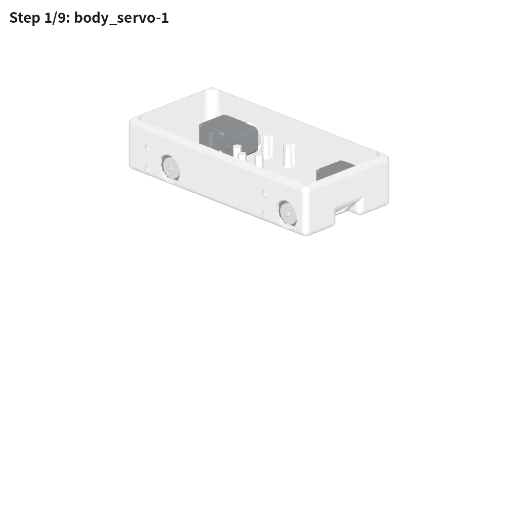
Attach the pre-built units to the body (body_servo).
Step 1: place body_servo#
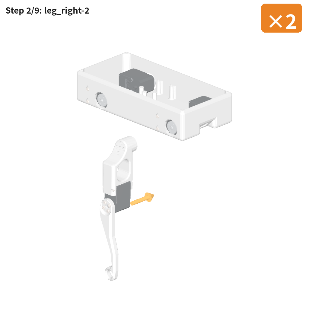
Step 2: attach leg_right (first)#
Insert the leg link onto the servo horn at the rear of the body (coaxial φ3.0 mm ×4).
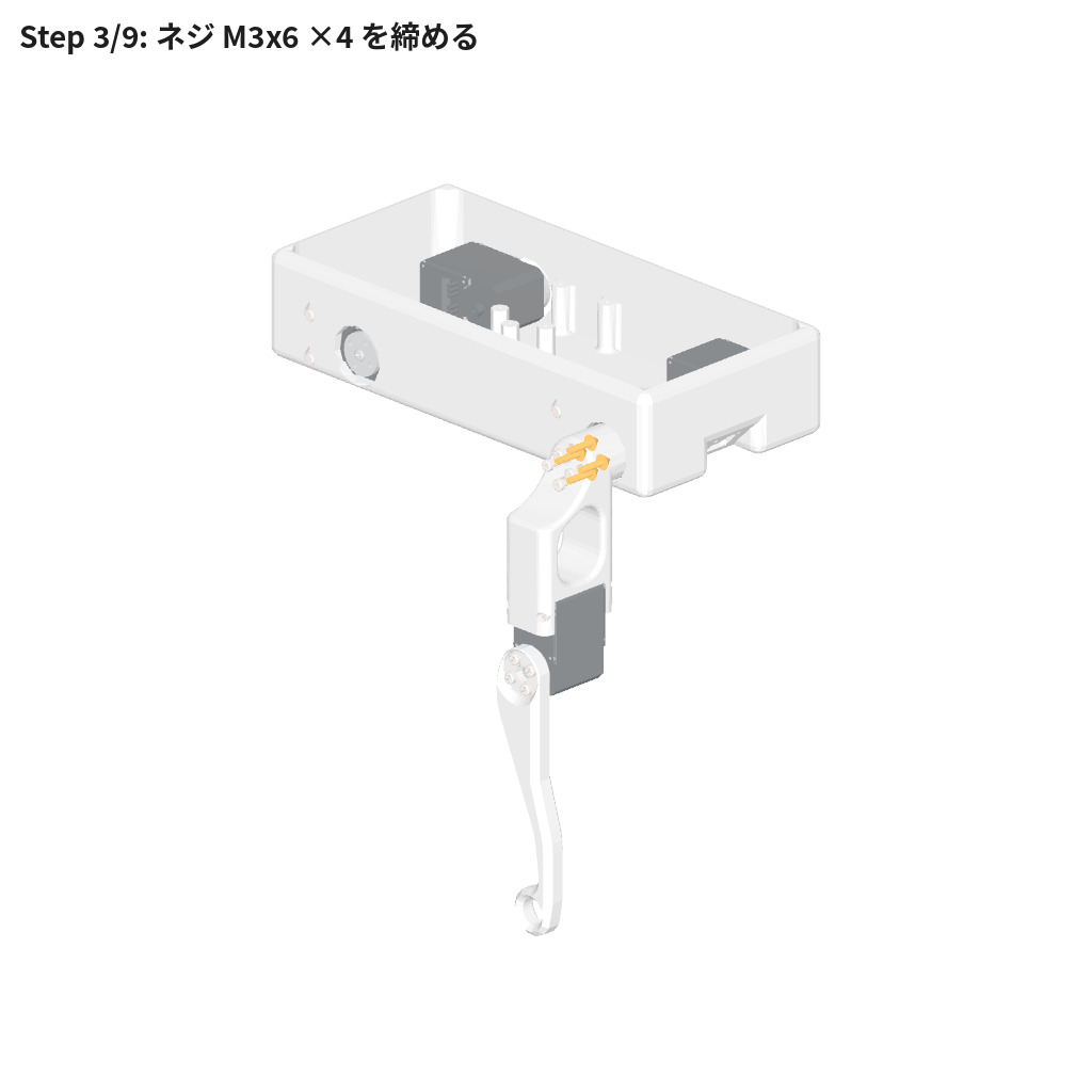
Step 3: 🔩 tighten M3x6 ×4#
Step 4: attach leg_right (second)#
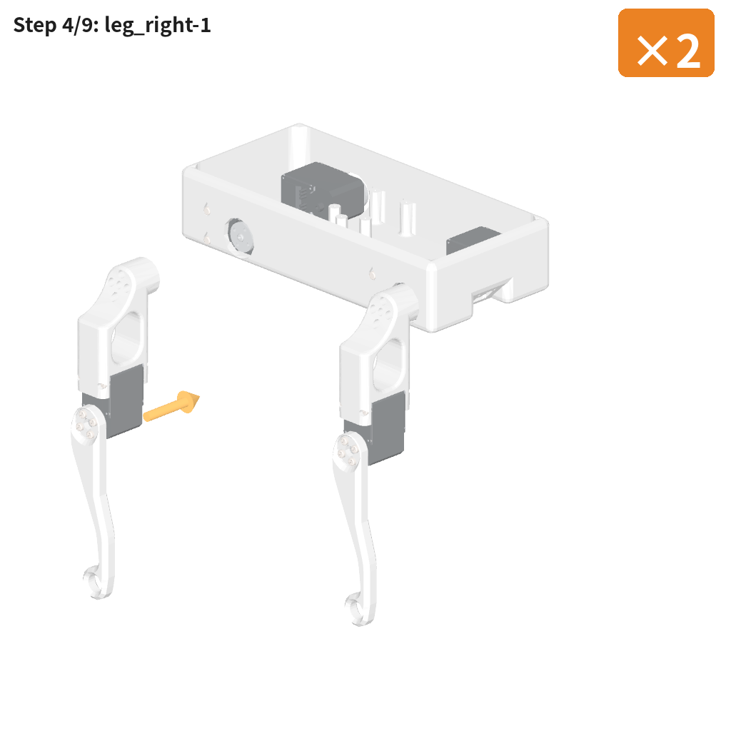
Step 5: 🔩 tighten M3x6 ×4#
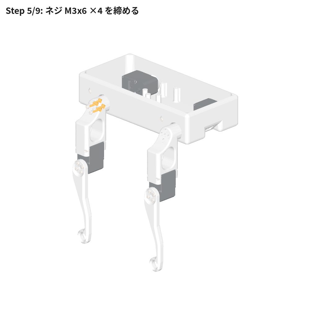
Step 6: attach leg_left (first)#
Insert onto the servo horn on the other side. It goes in the opposite direction to the right legs.
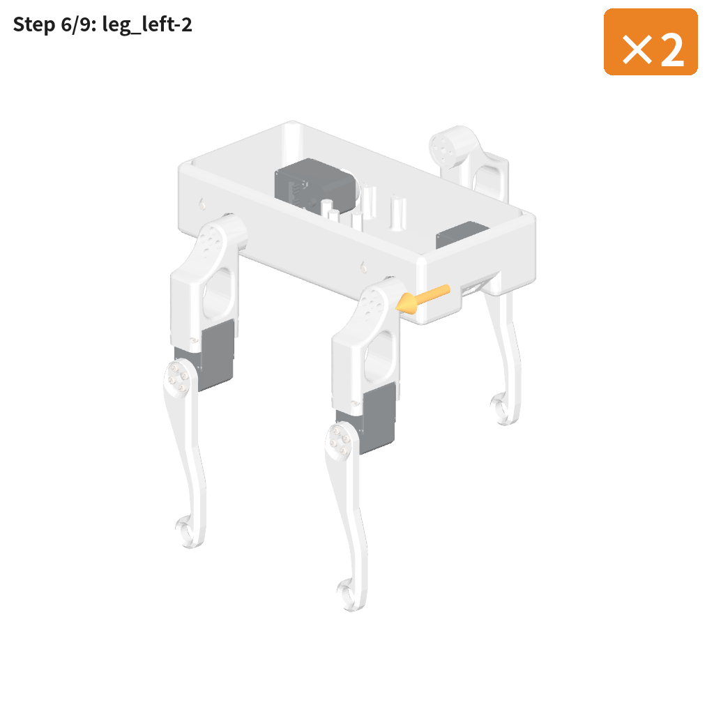
Step 7: 🔩 tighten M3x6 ×4#
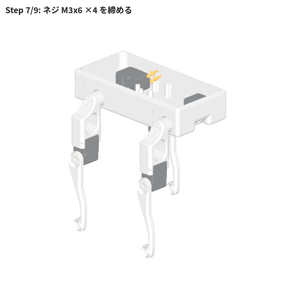
Step 8: attach leg_left (second)#
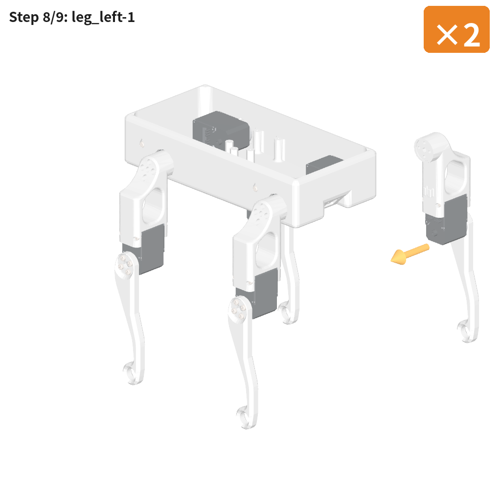
Step 9: 🔩 tighten M3x6 ×4#
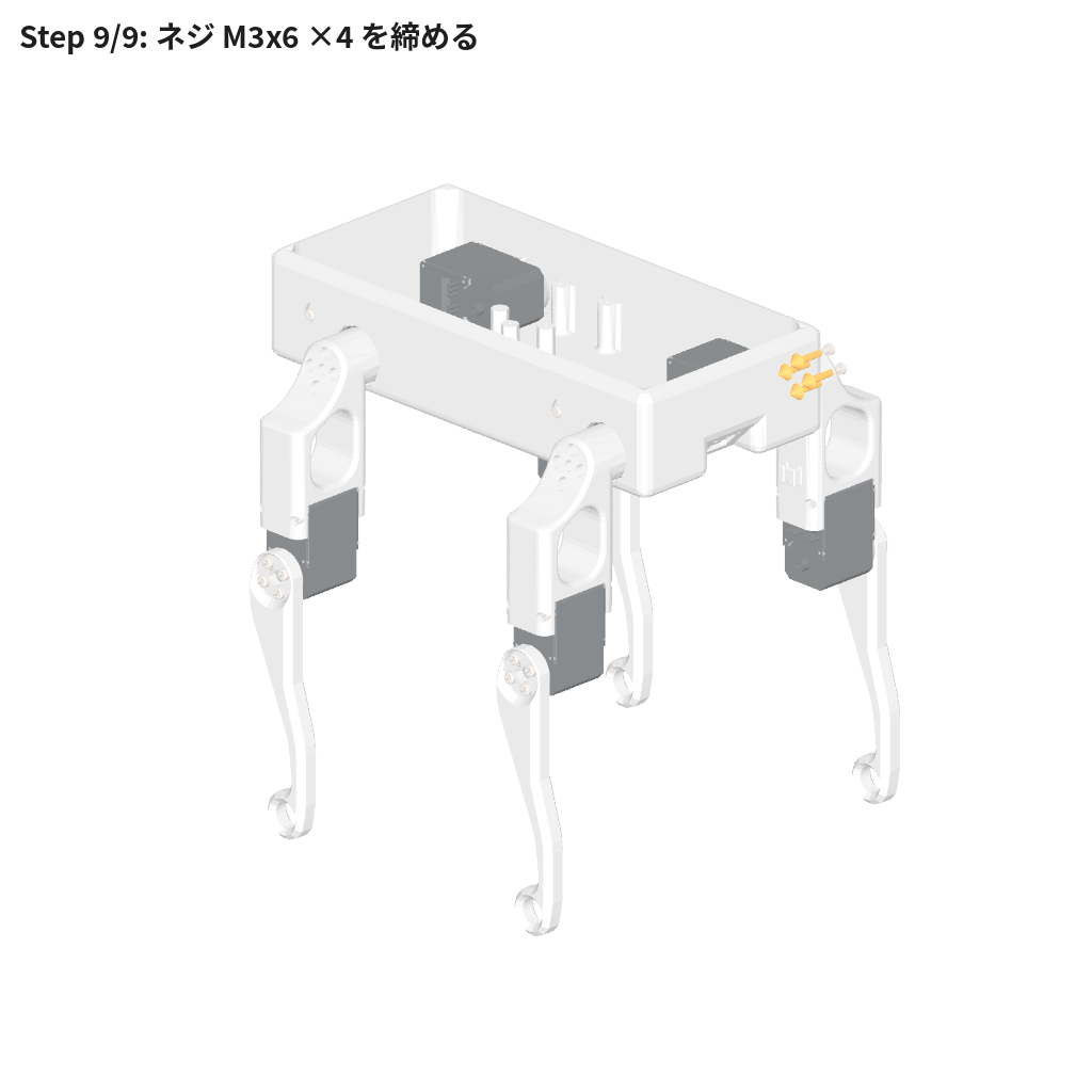
The robot is complete. For wiring and the zero point, see Walking the real robot.
The CAD data was exported with solidworks_urdf_exporter2.