Learning to walk (reinforcement learning)#
The chapter 13 quadruped walks with a policy trained by reinforcement learning. The training side, which did not fit in the book, is supported here. What reinforcement learning is, and what the tools it uses (PPO, MuJoCo, mjlab) are, is in What reinforcement learning is.
Try it in the browser#
A simulation that runs the trained policy in the WebAssembly build (the form that runs inside a browser) of the physics simulator MuJoCo. The same neural network you flash onto the robot runs a 50 Hz control loop inside the browser. Use the sliders to change the forward and turning commands. Push shoves the body sideways; “RL policy (with IMU)” is the policy from Balancing with an IMU.
The physics is the same as in training. Only the four foot spheres touch the ground, the servos are position-controlled (kp 25, kd 0.5) with a viscous damper for the back-EMF and gearbox friction, and every command reaches the servo 20–35 ms late (a band around the 27 ms measured on the real robot).
Note
The first load downloads about 16 MB (the WebAssembly build of MuJoCo and the robot model). The simulation’s UI labels are in Japanese.
The control switch compares the sin/cos gait of section 13.5 in the book (state
machine + trot, a gait that moves the legs in diagonal pairs) with the reinforcement
learning (RL) policy. The sin/cos gait lifts the swing leg along a sine arc and
converts it to joint angles with two-link inverse kinematics (IK, working out the
joint angles from where the foot should be; section 13.3); it is the book’s
sample code src/gait.cpp + src/leg_ik.cpp ported to the browser as is. This
robot is asymmetric front to back, though, so the gait changes completely with the
direction: with the same 0.02 m stride (slider ±0.05) it barely moves forward
(0.006 m/s) but goes backward at 0.10 m/s. Forward, the slider at 0.12 (0.048 m
stride) gives 0.06 m/s, and at 0.15 it tips over sideways about one run in eight.
Tuning the coefficients by hand can only suit one direction — that is the motivation
for RL.
What reinforcement learning is#
Reinforcement learning does not teach the robot the right movements. It lets the robot find them by trial and error: good results earn points (the reward), and the robot gradually picks up the ways of moving that earn more. The rewards for this quadruped include:
points for moving at the commanded speed
a few points for staying up; the run is cut short if the body tilts too far or drops too low
a penalty when the body height drifts from its target
a penalty for spinning the joints faster, or pushing them harder, than needed
Doing this over and over on the real robot would take forever and break it, so the training happens in a physics simulation, with 4096 robots walking at once. What is left when training ends is the policy, which turns observations into the next joint targets, and that is what goes onto the Arduino.
The tools and terms involved:
Name |
What it is |
|---|---|
PPO |
Proximal Policy Optimization. One of the procedures (algorithms) for improving a policy step by step, known for keeping each update from changing the policy too much (paper, 2017) |
MuJoCo |
Multi-Joint dynamics with Contact. A physics simulator for bodies made of joints moving while in contact with the ground and other objects. Developed by Roboti LLC, acquired and made free by Google DeepMind in 2021, and open-sourced in 2022 (official documentation). The browser simulation above uses it |
mjlab |
A framework for building reinforcement learning environments on MuJoCo. It runs many copies of MuJoCo side by side on the GPU with MuJoCo Warp, and its environments are written in the style of NVIDIA’s Isaac Lab (mujocolab/mjlab). Training with mjlab needs an NVIDIA GPU (without one, see Training the walking policy yourself) |
unitree_rl_mjlab |
Unitree’s code for training its own robots with mjlab (unitreerobotics/unitree_rl_mjlab). This book trained its robot by plugging this robot’s definition and rewards into it |
rsl_rl |
A reinforcement learning library for robots from the Robotic Systems Lab at ETH Zürich. The PPO used here is its implementation (leggedrobotics/rsl_rl) |
sim2real |
Taking a policy trained in simulation to the real robot. Simulation and hardware never match exactly, so training allows for the difference (“Training code” below) |
Inside the policy#
A single small multi-layer perceptron (MLP: fully connected layers stacked up, the plainest kind of neural network) does all the walking, small enough to run inference every cycle on the Arduino UNO R4.
Input (observation) |
87 dimensions = command (vx, vy, wz), gait phase (sin/cos), 8 joint angles, 8 joint velocities, the previous 8 actions (an action is the policy’s output), each with 3 steps of history |
Network |
Fully connected [96, 64], ELU (Exponential Linear Unit) activation |
Output |
8 (one per joint). Servo target = home angle + 0.25 × action. The home angle is the joint angle in the home pose (the reference standing pose the robot starts walking from) |
Control period |
50 Hz (0.02 s), gait clock 0.32 s |
Sensors |
Joint angles and velocities only. No IMU (inertial measurement unit, a sensor for the body’s tilt and rotation rate; the robot has none, so the policy cannot see the body’s attitude. The version with an IMU is in Balancing with an IMU) |
With no abduction joints (joints that swing a leg out sideways) it cannot move sideways (vy); it turns by taking longer steps on one side.
Performance in simulation: 0.120 m/s (0.48 body lengths/s) for a forward command of 0.12 m/s, and 0.148 m/s for the maximum command of 0.15 m/s, so it tracks the command closely. Turning reaches 0.213 rad/s for a 0.3 rad/s command. The diagonal trot runs at 3.13 Hz (gait period 0.32 s), the same at every speed. All of these were measured with the same model and controller as the simulation above, five 20 s runs each, averaging the last 10 s. The low speed is a property of the robot, set by the servos’ no-load speed, not a failure of training.
Training code#
Training uses PPO (rsl_rl) in mjlab (unitree_rl_mjlab), written as an overlay (the upstream code is used as is, and only the files this robot needs are laid over it) that swaps in the robot definition, rewards and environment settings:
The full robot description (URDF, the robot description format used by ROS and others; MJCF, MuJoCo’s model format; meshes; RViz config; with a script that reproduces the MJCF from the SolidWorks export): docs/os-on-arduino/code/13_quadruped/arduino_os_quad_robot
For sim2real it was trained with randomised friction (0.4–1.1), added mass (0–250 g for the electronics), zero-point error (±1.7°), joint angles (±8.6°) and more, then fine-tuned (robustified) with further randomised reset poses and velocities. That is why it still walks if the assembly is a few degrees off.
How to retrain it yourself is in Training the walking policy yourself, for when you want to change the rewards or the speed limit, and how to run it on Google Colab if you have no GPU.
Walking the real robot#
Use the chapter 13 sample code: docs/os-on-arduino/code/13_quadruped/, obtained as in
Chapter Support (the same as
code/13_quadruped/
on this site). The commands below assume you are in docs/os-on-arduino/code.
The trained policy is in include/arduino_quad_policy.h, and it is the same policy
as the browser simulation above.
Three values have to match your robot. The servo IDs follow the
assembly table, and the rotation directions (sign) are fixed by
how the legs are mounted, so a robot built as in the book keeps the values already in
include/quad_calib.h. That leaves the zero point, which is written into each
servo’s EEPROM (memory that keeps its contents with the power off) with the legs
held straight. Because it lives in the servos, the
firmware does not need editing.
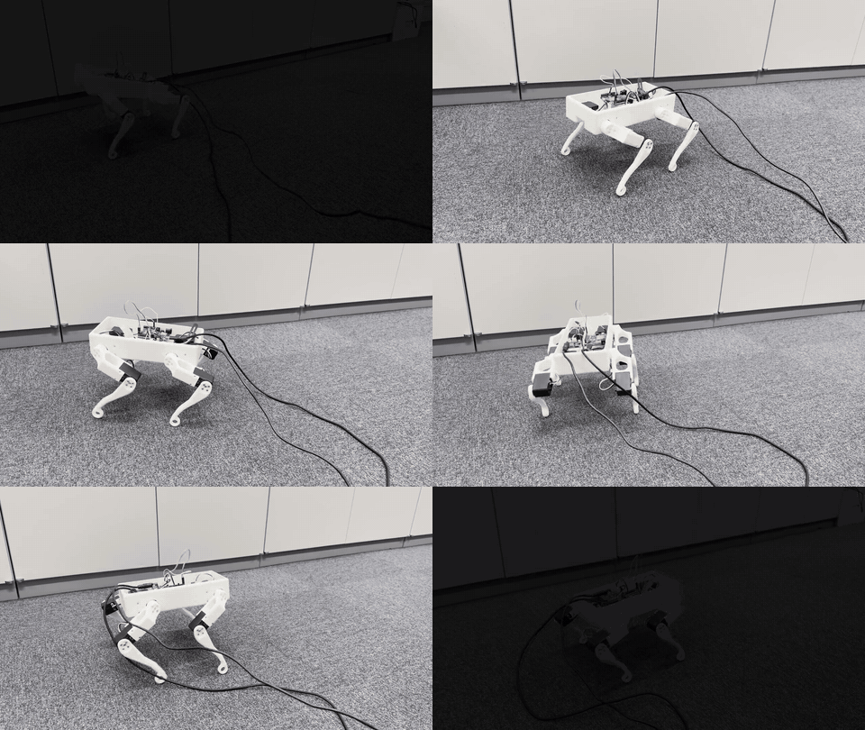
The book’s robot (8 servos driven by your own OS) walking (1.5x speed)#
1. Wiring#
The driver board and the Arduino UNO R4 WiFi sit side by side inside the body. The eight servos are daisy-chained into the board’s 3-pin connectors (D V G).
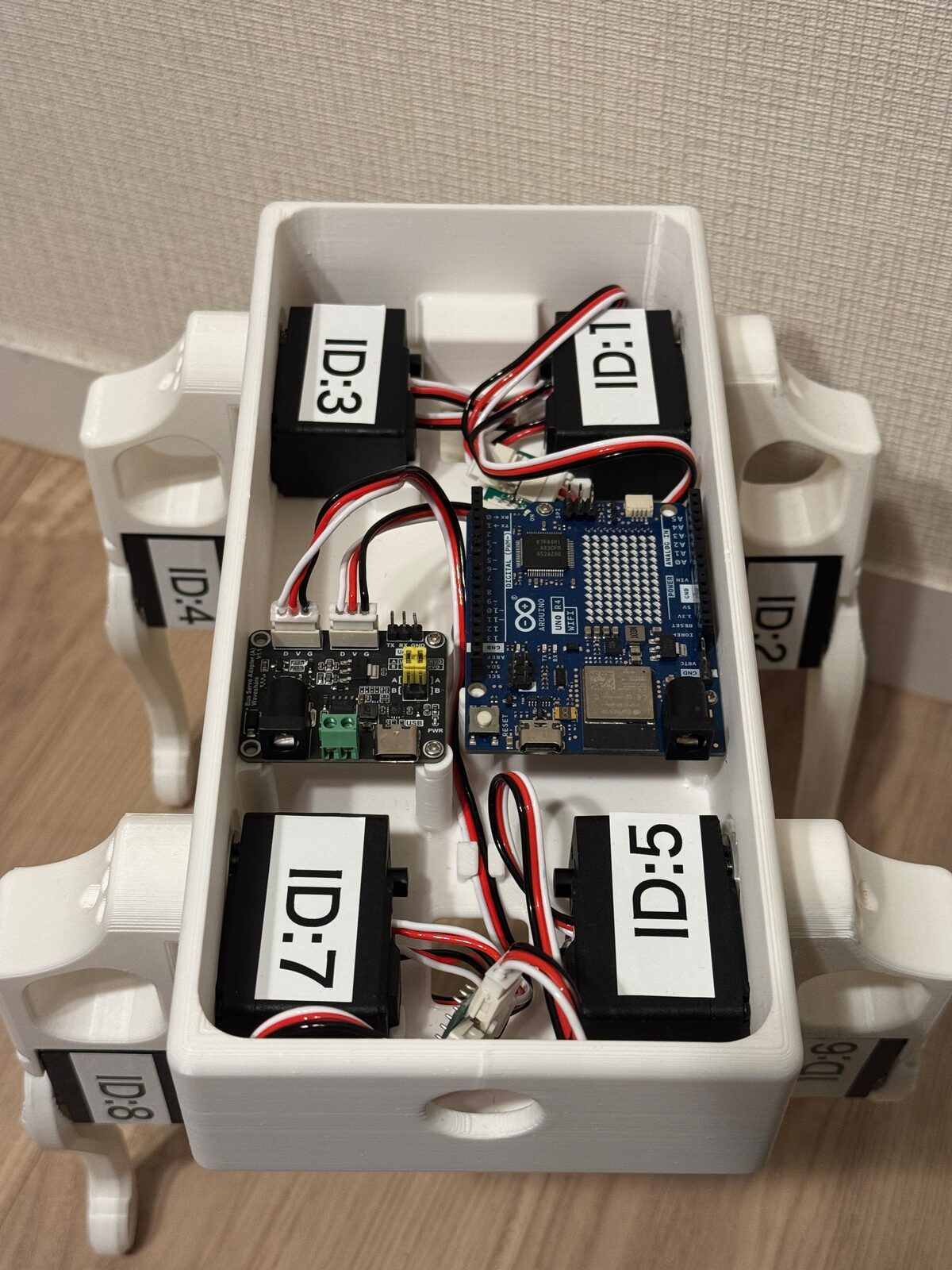
Inside the body. Each label must sit where the assembly table puts that ID#
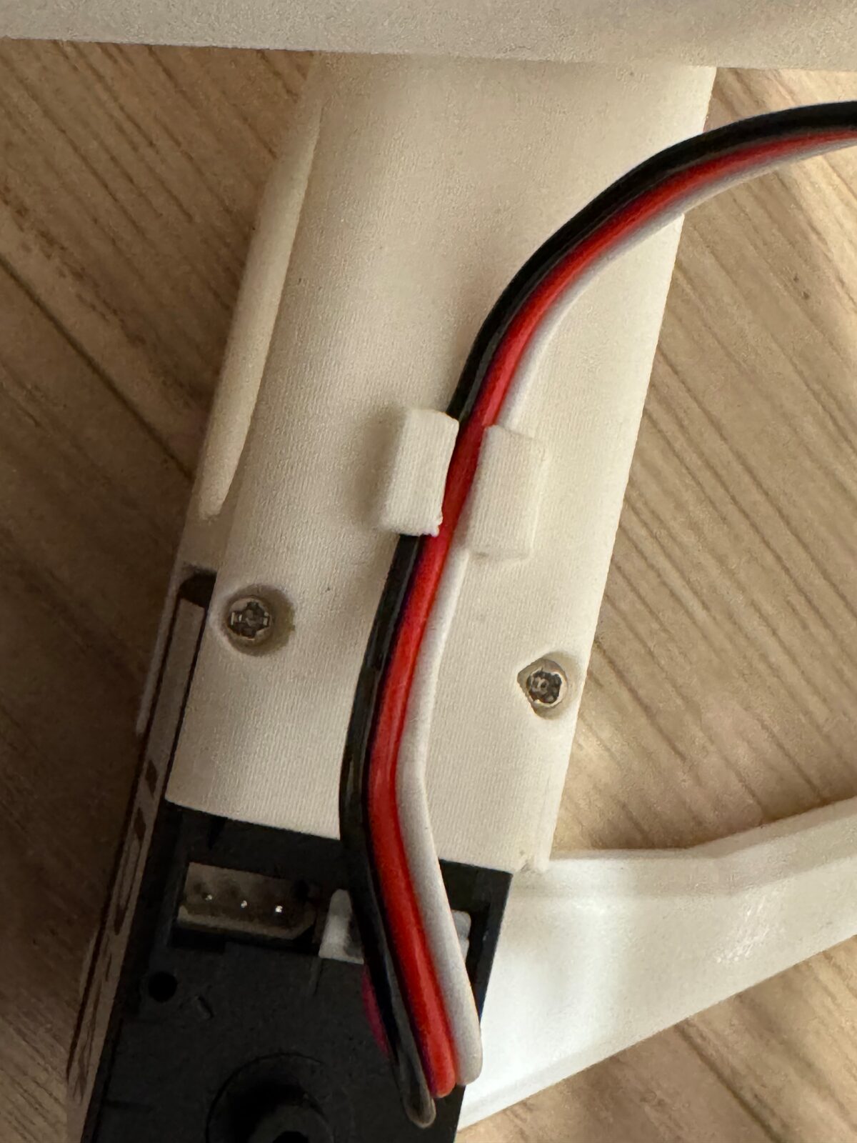
The knee servo’s cable runs through the hook on the leg bracket into the body#
Connect the board’s UART (serial) header to the Arduino with three wires. On this board TX goes to TX and RX to RX (“Know this before wiring” in Bill of materials (BOM) — 8-DoF quadruped).
Driver board |
Arduino |
|---|---|
TX |
D1 (TX→1) |
RX |
D0 (RX←0) |
GND |
GND |
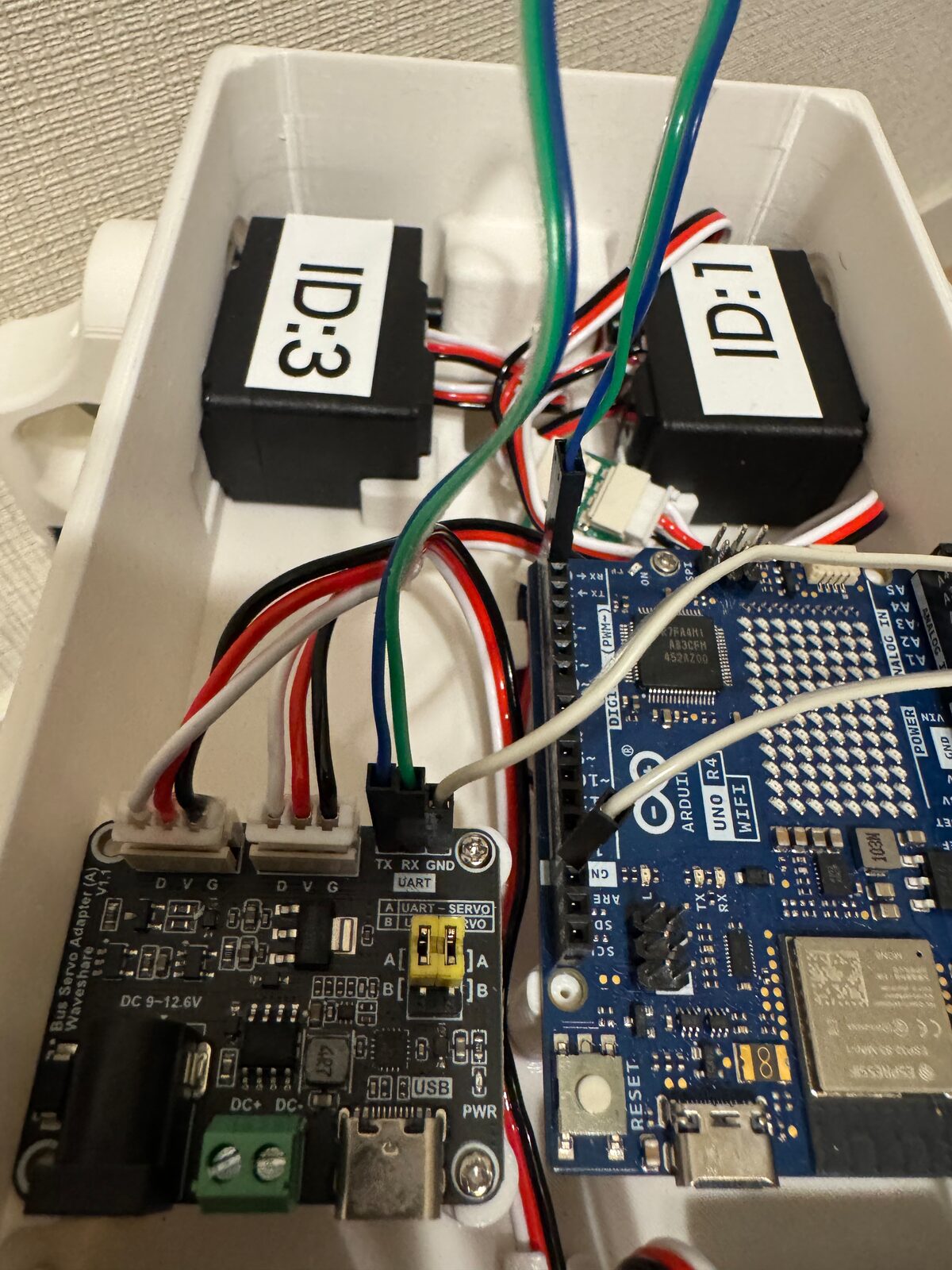
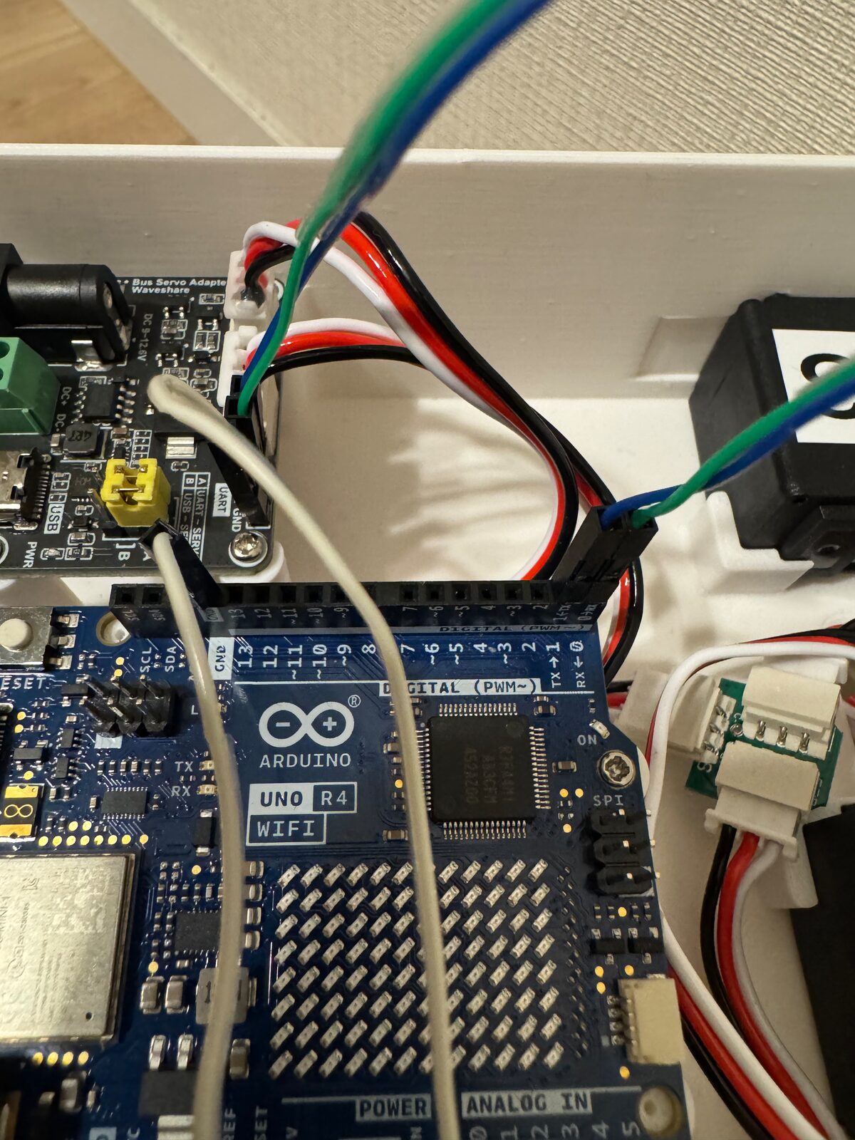
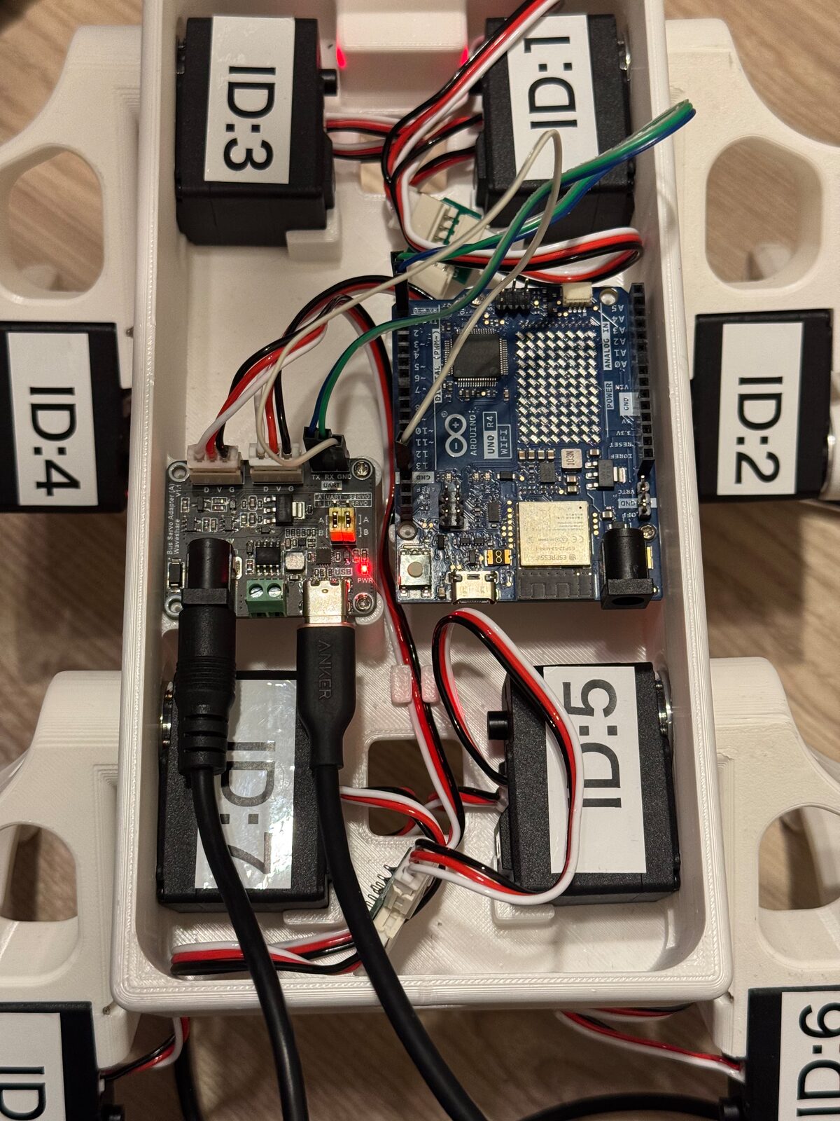
Wiring done. The board takes power on the DC jack, and USB Type-C when the PC drives the servos#
2. Set the zero point from the PC#
Put the driver board’s jumpers on B (USB-SERVO) and connect the board’s USB Type-C to the PC. The Arduino is not involved; the PC drives the servos directly.
cd 13_quadruped/host
uv sync                                  # installs numpy and feetech-cli

uv run python quad_host.py scan          # do all 8 answer?
uv run python quad_host.py zero          # make the straight-leg pose the zero point
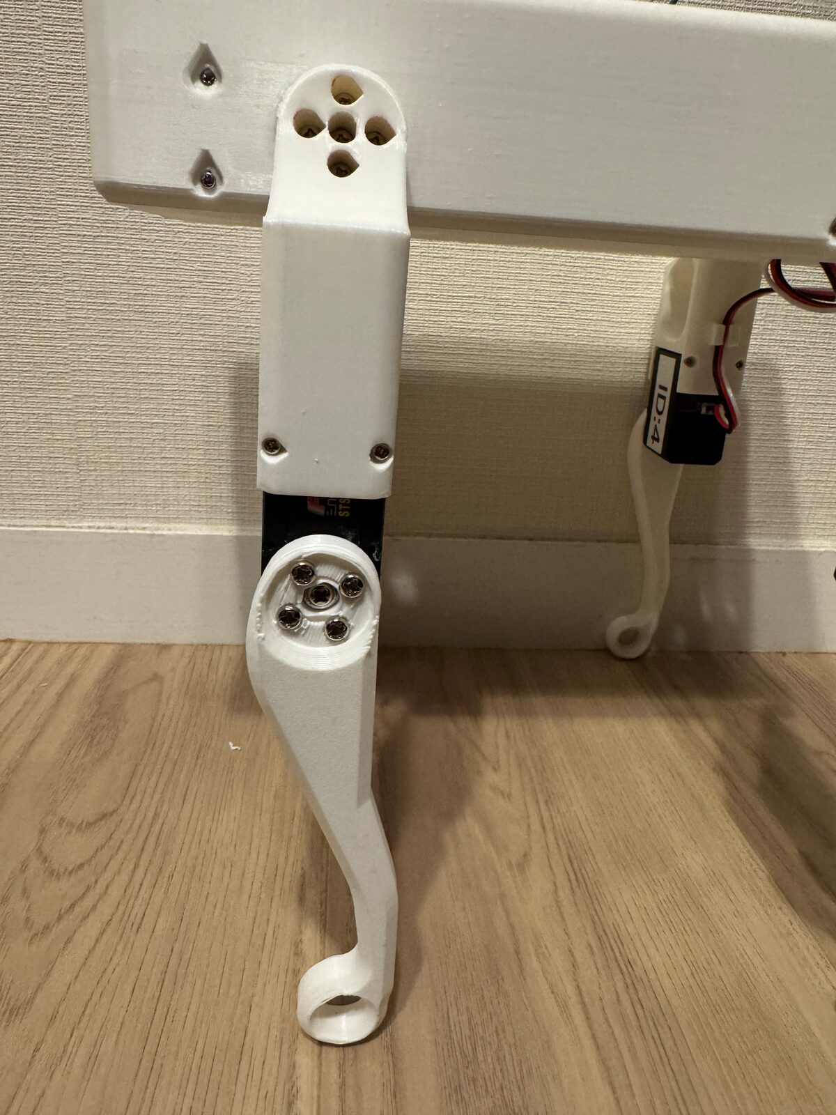
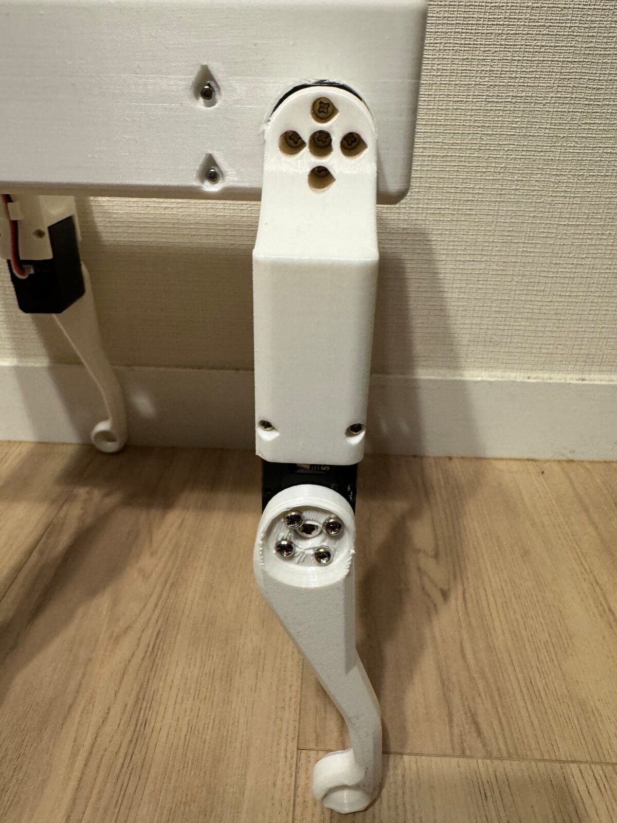
zero switches the torque off and waits for all four legs hanging straight down,
hip to foot (hold the robot up or suspend it). The CAD is drawn so that this pose
is 0 degrees. Press Enter and the zero point goes into the EEPROM of all eight servos,
which are then checked to read 2048. It survives a power cycle.
With the zero point in place, the PC can already stand the robot up and walk it.
uv run python quad_host.py stand         # hold the home pose; Ctrl-C goes limp
uv run python quad_host.py teleop        # walk from the keyboard (the PC runs the policy)
Do stand with the robot suspended first and check that all four legs take the
same shape with the knees pulled back. If one leg comes out mirrored, that leg’s ID or
mounting is wrong.
The teleop keys are below. Each press of w adds 0.02 m/s of forward speed, and
space stops the robot.
Key |
Action |
|---|---|
|
forward speed ±0.02 m/s |
|
turn rate ±0.05 rad/s |
space |
stop and hold the home pose |
|
every joint to 0 degrees (legs straight). Suspended only |
|
stop, go limp and quit |
3. Flash the Arduino and walk#
Put the jumpers back on A (UART-SERVO), connect the Arduino to the PC over USB and flash it.
cd ../..                                  # back to code from host (step 2)
uv run pio run -d 13_quadruped -t upload
When flashing finishes the Arduino boots and rises to the home pose over 2 seconds. From here the Arduino runs the policy, and the PC only sends velocity commands. To drive it from the keyboard:
cd 13_quadruped/host
uv run python quad_host.py serial        # send velocities over the Arduino's USB serial
The keys are the same as teleop, with two differences. x does not go limp: the
robot stops and keeps standing in the home pose. And if commands stop arriving for 0.3
seconds, the Arduino stops by itself and holds the home pose (for when the PC hangs or
the cable comes out).
You can also type commands straight into a serial monitor
(uv run pio device monitor -b 115200 in docs/os-on-arduino/code).
Command |
Action |
|---|---|
|
forward/inverse kinematics (FK/IK) round-trip test. The legs do not move |
|
move to the home pose over 2 s and hold |
|
the sin/cos gait of section 13.5 (walking without learning). Try it suspended |
|
walk with the trained policy, e.g. |
|
move every joint to 0 degrees and hold. Suspended only |
|
switch the torque off |
While walking, a line like this appears every second (the book’s robot, rl 0.15 0):
loop avg 5770 us max 5797 us late 0/51 skipped 0 read_fail 0
loop avg is the time one pass takes; anything inside the 20 ms control period
(50 Hz) is enough. skipped counts control periods that were dropped and read_fail
servos that did not answer; both should stay at 0. If they climb, suspect the
wiring or the power supply.
Warning
Power the 8 servos from the 12 V AC adapter or a battery. Never from the PC’s USB (stall current is 2.7 A per servo)
Do
standand the first walk with the robot suspended. With a wrong ID or mounting it does not walk badly, it thrashes
Tip
Rubber or silicone on the feet makes them slip less. The robot walks on bare plastic too, but on a hard, smooth floor such as wood flooring the feet slip more easily.
FAQ#
Can it get up after falling? — No. With no IMU it cannot observe its own attitude (even with training, the success rate was 1%). This is where adding an IMU pays off most. Balancing with an IMU adds an IMU to recover from pushes, but getting up is not trained yet.
Can it go faster? — With 45 rpm servos and 0.19 m legs, 0.05–0.2 m/s is what the hardware can do (0.16 m/s at the maximum command in simulation). The limit is the no-load speed, not torque, so going faster means changing the servos or the leg length.